MRV Communications TERESCOPE TS800/155 User Manual
Page 24
M R V C o m m u n i c a t i o n s , I n c . – I n s t a l l a t i o n M a n u a l
14
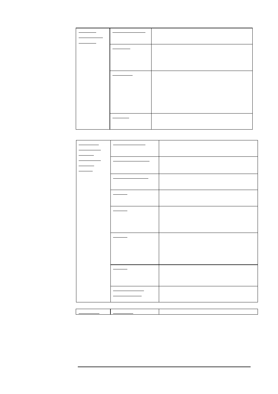
Air RX Flag LED
Green LED indicates signal received by the Airlink
receiver. Turns ON at the threshold level.
Laser Enabled LED
Red LED. Turns ON to indicate that laser in
enabled to transmit light.
F/O RX Flag LED
Green LED indicates Data received by the Fiber
Optic receiver. Turns ON at the threshold level.
Pins 1,2
Closed (25 ohm) = Internal DC power functional
Open = internal DC voltage not present in circuit
Pins 3,4
Air Rx alarm
Closed (25 ohm) = airlink optical power received
above threshold
Open = received optical signal below threshold
Pins 5,6
F/O Rx alarm
Closed (25 ohm) = received signal at fiber interface
above threshold
open = signal received at fiber receiver below
threshold
Pins 7,8
Laser Enabled Alarm
Closed (25 ohm) laser is enabled
Open = laser is disabled due to malfunction
Indicators
(7-segment
display,
LEDs),Dry
Contact
Alarms
Optical Power 7-
segment display
Digital readout indicates the Optical Power level
received by the Airlink receiver.
Alignment Telescope
For fine alignment.
Transmitter Mode
(Toggle 1)
ON position (up) for links above 150m distance.
OFF position (down) is for under 170m distance
Not Used
(Toggle 2)
Not used.
(No internal loopback function. For a complete
loop test, far-end loopback of airlink data can be
performed externally with fiber from Tx to Rx)
IP Address
(Toggle 3)
When the Switch toggle is on OFF position, the
TereScope’s IP address is the default one (shown on
the back panel label: 10.0.0.101). To set a new IP
address please refer to the “IP address setting
procedure for TereScope management card” file in
the Manuals CD. The new IP address is valid only
after the TereScope is powered off and on.
Selectors
(DIP Switch
Toggles)
--
shown in Figure
1.7
Data rate
(Toggle 4)
ON position (up) for Gigabit Ethernet,
OFF position (down) for 1.0625Gb/s FiberChannel