Warning, Caution – Multiquip MQ Power Portable Generator (Standard) DCA-125SSJU User Manual
Page 44
PAGE 44 — DCA-125SSJU SERIES (STANDARD) — PARTS AND OPERATION MANUAL — REV. #4 (06/03/03)
DCA-125SSJU SERIES — GENERATOR START-UP PROCEDURE (MANUAL)
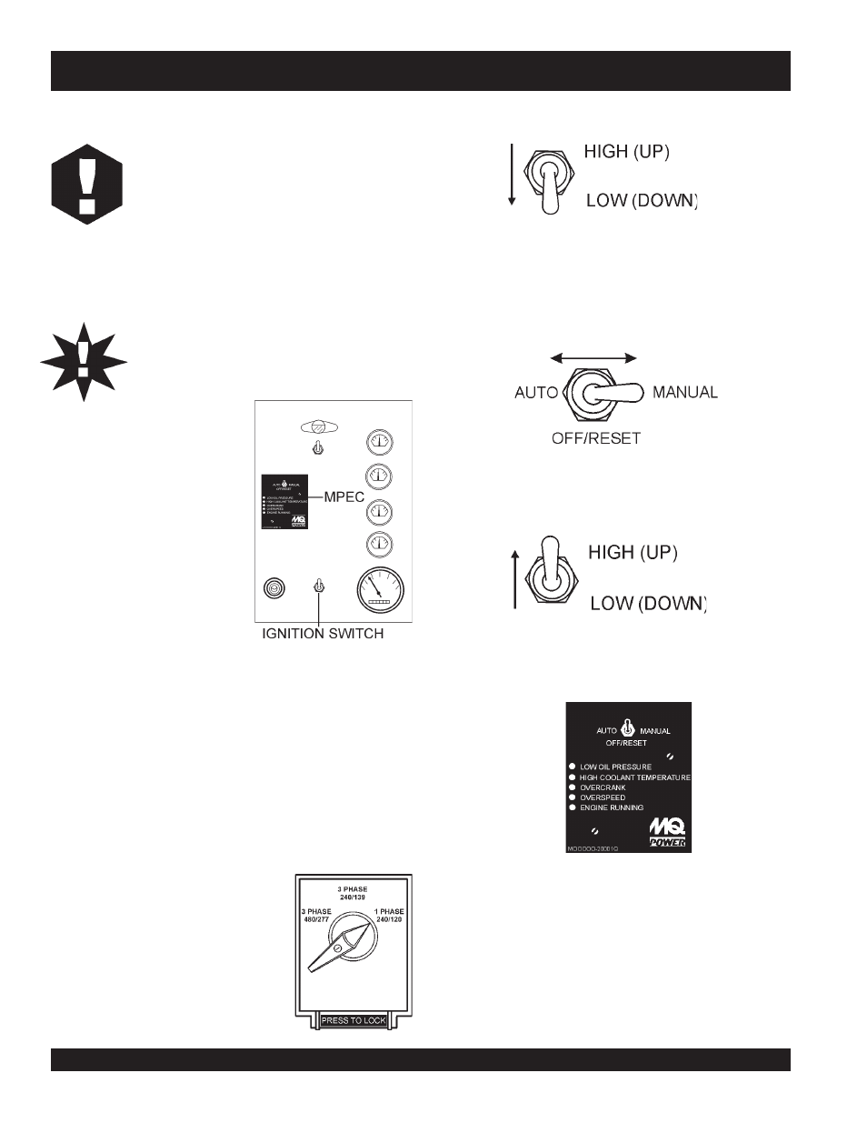
Figure 66. Auto-Off/Reset-Manual Switch
Figure 65. Engine Speed Switch (Low)
23. Set engine speed switch to “LOW ” (Figure 65).
25. Once the engine is warm and the engine is running properly,
set the engine speed switch to “HIGH
” (Figure 67).
24. Place the Auto-Off/Reset-Manual switch in the
“MANUAL
” position to start the engine (Figure 66). Once
the engine starts, let the engine run for 1-2 minutes.
Listen for any abnormal noises.
Figure 67. Engine Speed Switch (High)
WARNING:
WARNING:
WARNING:
WARNING:
WARNING:
The engine's exhaust contains harmful
emissions.
ALWAYS have adequate
ventilation when operating. Direct exhaust
away from nearby personnel.
NEVER! manually start the engine with the
main, GFCI or auailliary circuit breakers in
the ON (closed) position.
CAUTION:
Before Starting
Engine Operating Panel S/N 7500508~
Steps 20 thru 31 are referenced
for Engine Operating Panel S/N
7500508~ (Figure 63). This unit
does
not have a key ignition
switch or a throttle lever. It does
have an “
engine speed switch”
that is used in conjunction with
the MPEC unit.
Figure 63. Engine Operating Panel
S/N 7500508~
20. Perform steps 1 through 4 in the
Before Starting section
(page 41-42) as outlined in the
Manual Generator
Start-up Procedure (Engine Operating Panel up to
S/N 73002140).
21. In cold weather conditions, perform step 6 in the
Before
Starting section (page 42) as outlined in the Manual
Generator Start-up Procedure (Engine Operating Panel
up to S/N 7500508). Otherwise skip to step 22.
26.
Verify that the "Engine Running" status LED on the MPEC
unit (Figure 68) is "ON" (lit) after the engine has been started.
Figure 68. Engine Running LED (ON)
27. Continue operating the generator as outlined in steps 11
thru 19 (pages 42-43).
Figure 64. Voltage Selector
Switch
22. Place the voltage selector switch
in the desired voltage position
(Figure 64).