8. meter circuit board settings – Miller Electric XR Control User Manual
Page 25
OM-1594 Page 19
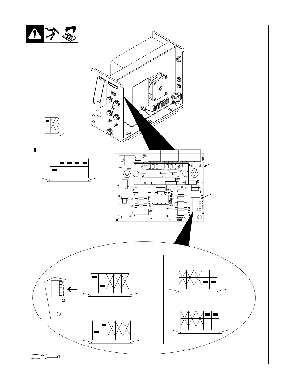
5-8. Meter Circuit Board Settings
Ref. 802 359 / Ref. 186 266
Tools Needed:
1/4 in
1
Meter Board PC2
2
DIP Switch S2
Set DIP switch S2 for type of
welding power source, and desired
wire feed speed display.
Reinstall hinged door and side
panel.
1
2
3
4
5
1
2
3
4
5
1
2
3
4
5
1
2
3
4
5
Or
Or
Meters/Minute
Inches/Minute
Digital Meter Display
Arc Voltage Sensing Using Voltage Sensing
Lead For Welding Power Source That Does
Not Support Pins F And H
Voltage Sensing Function
Arc Voltage Sensing Using Feedback From
Welding Power Source That Does Support
Pins F And H
1
2
X Means switch position does not affect
specified function.
. Means switch must be in this position.
2
1
.
For sense lead, connect PLG51 to PLG50.
Before feeder can be used with a power
source that does not support pins F and H, a
voltage sensing lead must be installed in feed-
er. Volt sensing lead kit 209867. See section
5-7 for information regarding installation of
voltage sensing lead.
For voltage feedback, connect PLG51 to
PLG52.
1
2
3
4
5
Switch settings from the factory.