Owner’s manual, Wiring diagrams, Continued) – Master Lock MGH8500AIE User Manual
Page 17
17
117846
OWNER’S MANUAL
Red
Yellow
Green/Yellow
Grn/
Ylw
Grn/
Ylw
Grn/
Ylw
Green/
Yellow
Green/
Yellow
Green/Yellow
Green/
Yellow
Green/
Yellow
To Roll Cage
To Alternator
Ground
Blue
Red
Black
Gray
Gray
Blk
Blk
Blk
Black
Red
Red
Red
Red
Red
Red
Red
Red
Green
Green
120/240V
20A/30A
Receptacle
120/240V
20A/30A
Receptacle
120V, 30A
Receptacle
120V, 15A
Receptacle
120V, 20A
Receptacle
White
Wht
Wht
Wht
White
White
White
Auto-Idle
Auto-Idle
Control Board
P2
P5
P1 P4 P3
Circuit
Breaker
20A
Circuit
Breaker
20A
Circuit
Breaker
45A
Circuit
Breaker
45A
T2
T1
T3
T4
T1
T2
T3
T4
Rotor
Diode
Diode
Green
Red
Black
Blue
Stator
110/120V
T1
T2
T3
T4
L2
L1
110/120V
220/240V
Auxiliary
Phase
Stator
White
Brown
Capacitor
White
White
Main
Windings
GFCI
LINE
W
H
IT
E
H
O
T
Duplex
Hour
Meter
Gray
Gray
Gray
Blue
Blue
P5-2
P5-4
P5-1
P5-3
To
Auto-Idle
Solenoid
To
Power Supply
On Engine
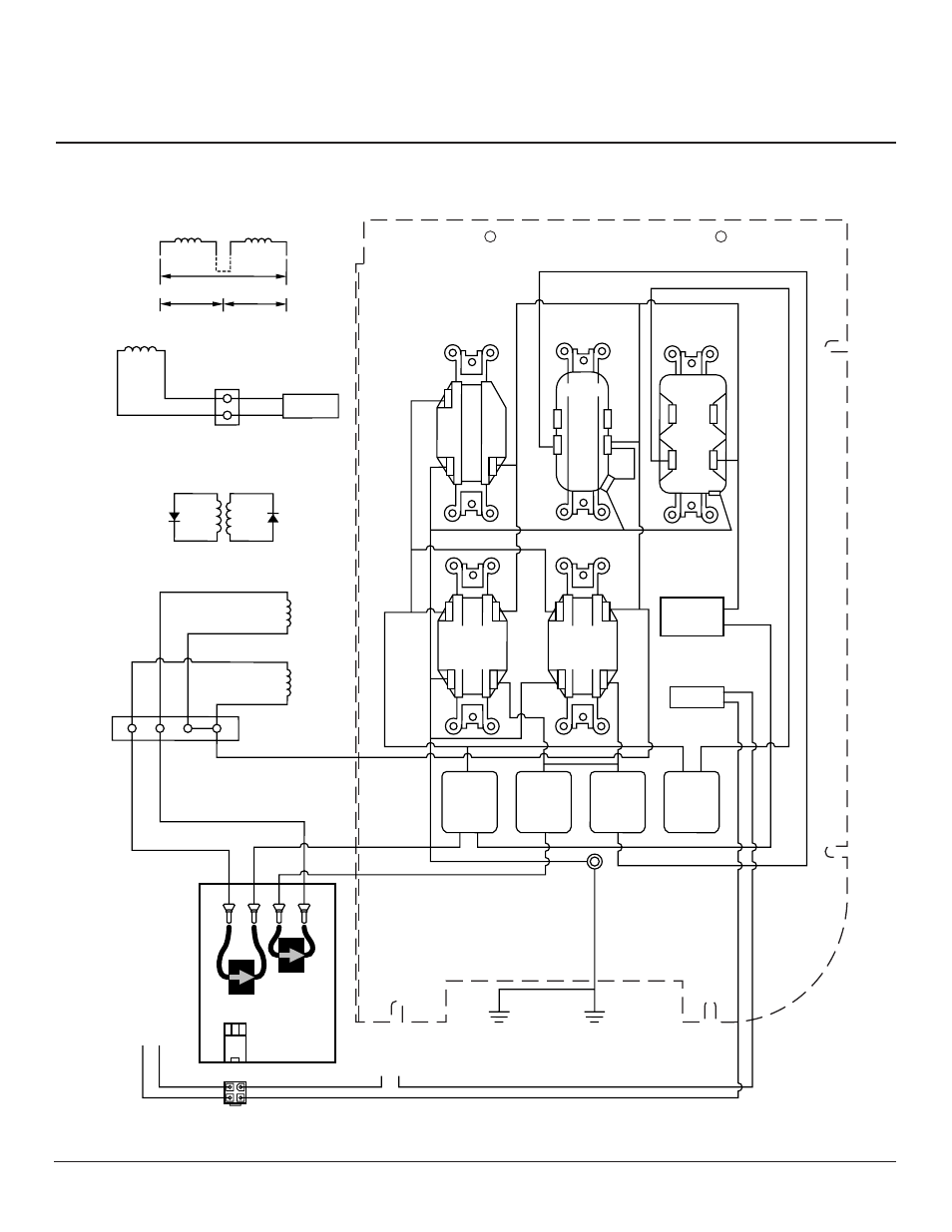
Figure 23 - Wiring Diagram, Model MGH8500AIE
WIRING DIAGRAMS
(Continued)