Owner’s manual, Operation, Continued auto-idle operation – Master Lock MGH8500AIE User Manual
Page 13: Adjusting the idle speed, Hours 1/10
13
117846
OWNER’S MANUAL
Reset
Reset
Reset
Reset
Reset
Reset
120
Volt
Auto
Idle
200 V
p;t
Sele
ctor
Off
On
RESE
T
TES
T
ENM
0000
0005
HOURS
1/10
OPERATION
Continued
AUTO-IDLE OPERATION
IMPORTANT: Never start engine with elec-
trical loads connected. Start engine before
adding electrical loads.
1. If engine is cold, turn the Auto-Idle
switch OFF (see Figure 19).
2. Start engine. Allow engine to warm up
with no load for five minutes.
3. Turn Auto-Idle switch ON. Engine will
slow to idle speed. Engine idle speed
is preset. Idle speed adjustment should
not be necessary.
4. Operate generator according to speci-
fications outlined in owner's manual.
5. Engine will automatically increase to
normal operating speed when you plug
load into any generator outlet.
WARNING: Always set the idle
speed before turning on the Auto-
Idle. If idle speed is not set, the
larger resistor on the control board
may become hot. Heat from the
resistor may damage the protective
coating on the control board.
Note: MGH10000C Only - The 250
Volt/50 Amp receptacle is not con-
nected through the Auto-Idle circuit.
The Auto-Idle switch must be turned
off to get full power out of this recep-
tacle (see Figure 19).
6. The Auto-Idle system should be turned
OFF when generator is shut down.
Adjusting the Idle Speed
IMPORTANT: Adjust the idle speed only:
• If the idle speed becomes too high.
• If the engine idle speed will not regulate (en-
gine idles and speeds up again and again).
1. Turn Auto-Idle switch OFF. Start en-
gine. Allow engine to warm up with no
load for five minutes.
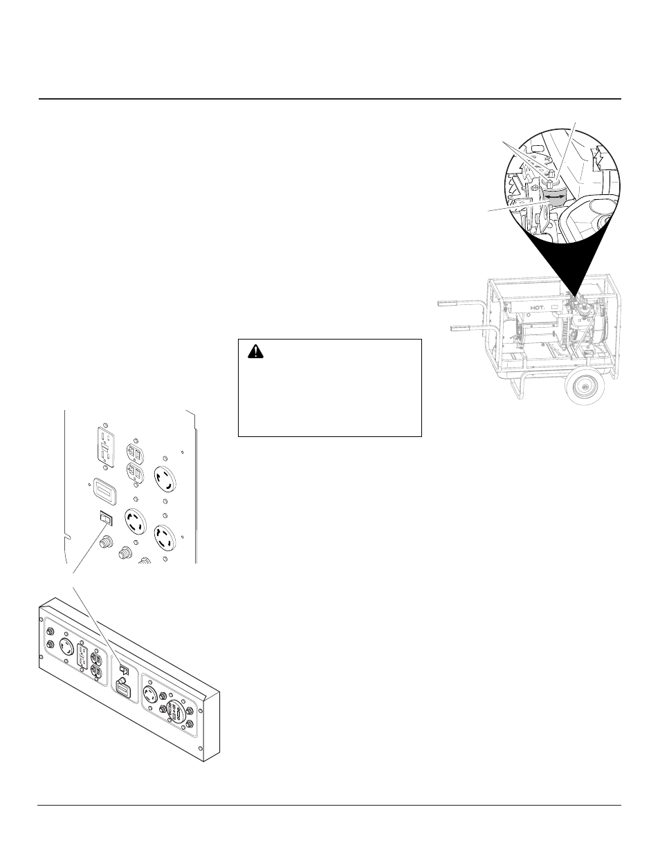
Figure 20 - Solenoid Bracket Location
(MGH10000C Shown)
Figure 19 - Control Panel
Auto-Idle Switch
2. Locate Auto-Idle solenoid. The Auto-
Idle solenoid is located between the
alternator and the engine when viewed
from the top of the generator (see Fig-
ure 20).
3. Loosen two M7 nuts.
4. Rotate solenoid (located under the
solenoid bracket) left or right to adjust
Auto-Idle speed (see Figure 20).
5. With a volt meter, check the no-load
output voltage at the 120-volt duplex
receptacle. At proper idle speed (3000
minimum RPM) the meter should read
50-60 volts. Lower settings will cause
the Auto-Idle to not operate properly.
6. After reaching proper idle speed,
tighten M7 nuts to secure solenoid to
mounting bracket (see Figure 20).
120/2
40V
TWIS
TLOC
K
120/2
40V
TWIS
TLOC
K
120V
TWIS
TLOC
K
120V
GFCI
120V
HOU
R ME
TER
AUTO
-IDLE
RESE
T
RESE
T
RESE
T
RESE
T
OFF
ON
RE
SE
T
TE
ST
EN
M
00000005
HOURS 1/10
MGH8500AIE
MGH10000C
M7 Nuts
Solenoid Bracket
Auto-Idle
Solenoid