Witch, Nstallation, Units with 6cen controls – Monessen Hearth B-Vent Specialty Gas Fireplace System DESIGNER SERIES User Manual
Page 13: Units with 6cn and 6clp controls, 10 f, S8600h, Gnd), Burner), Device that has been wet - replace it, Igure
Units with 6CEN Controls
1. Determine a convenient location within
twenty (20) feet and cut a hole large
enough to accommodate the wall
switch yet be covered with a wall
plate. It is not necessary to use a
wall box, but one may be used.
2. Route the wire provided through the 1/2
inch black plastic grommet in the unit.
3. Route the wire into the wall box, connect
it to the switch, mount the switch and
cover.
4. Set the wall switch to “OFF”.
5. Light the pilot according to instructions.
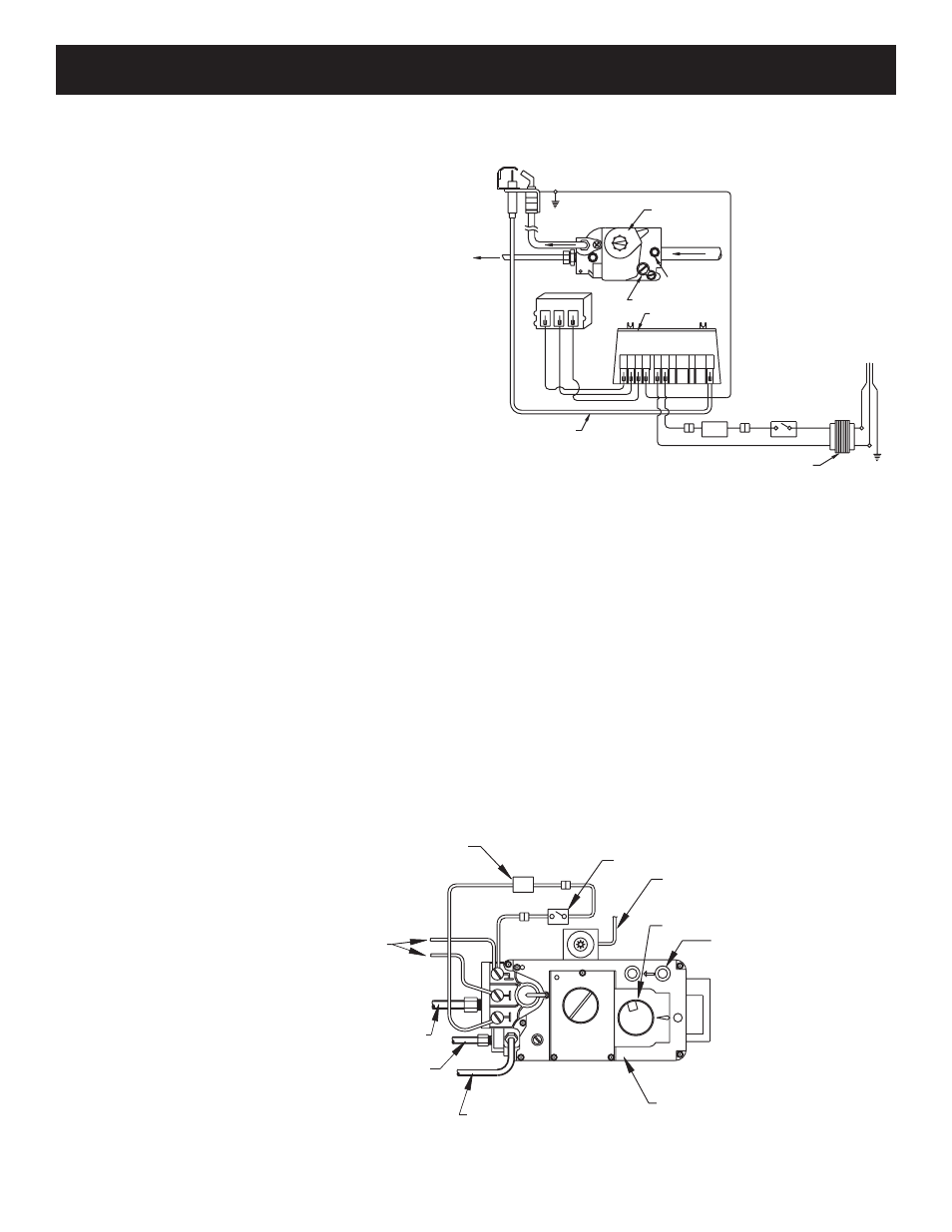
Units with 6CN and 6CLP Controls
The control system on this fireplace is powered by the thermocouple and operates on approximately 500mv
(one-half volt). All connections in the wiring must be clean and tight. The wall switch should be located as
near the fireplace as practical. Do not locate the wall switch so that more than the 25 feet of wire provided
must be used. Additional wire and splices will cause a voltage drop and may cause the control system to not
operate.
1. Determine a convenient location within twenty (20) feet and cut a hole large enough to accommodate the
wall switch yet be covered with a wall plate. It is not necessary to use a wall box, but one may be used.
2. Route the wire provided through the 1/2 inch black plastic grommet in the unit.
3. Route the wire into the wall box, connect it to the switch, mount the switch and cover.
4. Set the wall switch to “OFF”.
5. Light the pilot according to instructions.
W
ALL
S
WITCH
I
NSTALLATION
12
COMMONCOMMON
LINELINE
OFF
OFF
PVPV
ON
ON
ININ
PVPV
MVMV
MVMV
GAS CONTROL/ELECTRONIC IGNITION ROUTING
GAS CONTROL/ELECTRONIC IGNITION ROUTING
8
9
SPARK
S8600H
S8600H
24V, 60 Hz
24V, 60 Hz
100% SHUTOFF IP
100% SHUTOFF IP
90 SEC. L.O.
90 SEC. L.O.
TH-W
(OPT)
7
24V
24V
(GND)
5
6
Explosion hazard. Can cause
Explosion hazard. Can cause
serious injury or death.
serious injury or death.
This device can malfunction if
This device can malfunction if
it gets wet. Never try to use a
it gets wet. Never try to use a
WARNING
WARNING
GND
(BURNER)
PV
3
4
MV
1
2
MV/PV
device that has been wet - replace it.
device that has been wet - replace it.
PV-1A MAX. MV-1A MAX.
PV-1A MAX. MV-1A MAX.
CONTROL ADJUST SCREW
GAS CONTROL VALVE
POWER SUPPLY
120V. 60 Hz.
GND
TAP
GROUND
PILOT BURNER
GAS SUPPLY - IN
INLET PRESSURE
ELECTRONIC CONTROL
PILOT
SUPPLY
TAP
OUTLET
PRESSURE
GAS LINE-OUT
TO BURNER
WIRE TYPE 105
WIRE TYPE 105
DEGREE C. REPLACE
DEGREE C. REPLACE
WITH SAME OR
WITH SAME OR
EQUIVALENT.
EQUIVALENT.
PILOT GAS
SWITCH
WALL
LIMIT SWITCH
IGNITION WIRE
TRANSFORMER
F
IGURE
10
F
IGURE
11
OFF
OFF/PILOT/ON CONTROL KNOB
INLET PRESSURE TAP
TO PIEZO ELECTRODE
S.I.T.- 820 NOVA CONTROL
PILO
T
LIMIT SWITCH
LIMIT SWITCH
TP
TH
TP
TH
TO THERMOCOUPLE
GENERATOR
TO THERMOCOUPLE
PILOT TUBING
MANIFOLD TUBING
ON
WALL SWITCH
WALL SWITCH
53D9019.
Rev 3 11/07