English – GIGABYTE PHASER 4500 User Manual
Page 29
- 23 -
Hardw are Installation Process
English
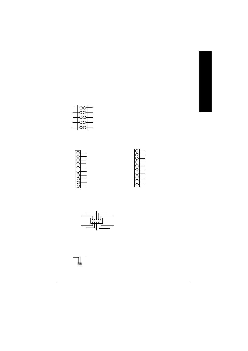
27) CI (CASE OPEN)
Ø This 2 pin connector allows your system to
enable or disable the “case open” item in BIOS
if the system case begin remove.
1
Signal
GND
1
SCACLK
VCC
GND
SCARST-
SCALED
SCAPWCTL-
SCAC4
SCAIO
SCAPSNT
SCAC8
23)MEMORY_STICK(Memory Stick Interface,White Connector) *
24)SECURE_DIGITAL
(Secure Digital Memory Card Interface,Red exide Connector) *
25)SMART_CARD_READER(Smart Card Interface,Black Connector) *
SMART_CARD_READER
1
GND
SD1
VCC3
SD3
SD4
SD5
SDCLK
SDLED
SD2
SDPWCTL-
SECURE_DIGITAL
1
5
SCACLK
SCAPWCTL-
VCC
SCAC4
SCAIO
SCARST-
SCALED
GND
SCAC8
SCAPSNT
MEMORY_STICK
1
GND
MS1
VCC3
MS3
MS4
MS5
MSCLK
MSLED
MS2
MSPWCTL-
Ø The device could be expanded for reading Flash
Memory, such as SD(Security Digital),
MS (Memory Stick) and Smart Card Reader
Connector. The Smart IC Card could
increase security in authenticating online
transactions; the card reader device ( inquire
local distributor) made by Third Party could
be purchased by users.
"*" FOR GA-7VAXP Only.
26)SCR (Smart Card Reader Header,Black Connector) **
Ø TThis MB supports smart card reader. To en
able smart card reader function an optional smart
card reader box is required. Please contact
your autherized distributor.
"**" FOR GA-7VAX Only.