Riser card, Front – Gateway E-4400 User Manual
Page 14
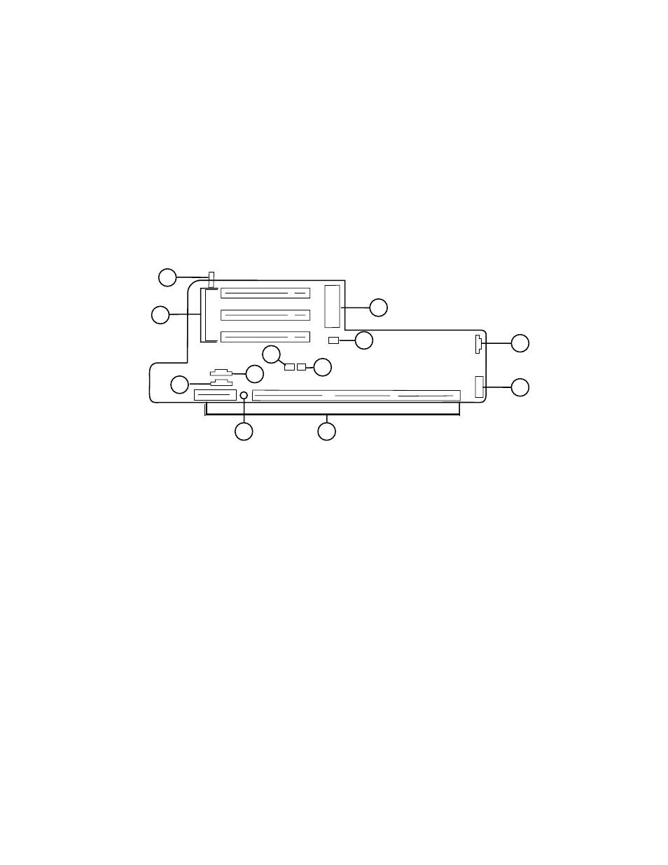
Riser card
7
Riser card
The riser card is mounted to the chassis by brackets at its base and two screws
at the top. The two screws attach the riser card to a bracket attached to the
power supply cage. The riser card contains most of the connectors and slots
used by the internal system components.
Front
A
SW1: Chassis intrusion switch
B
ATX power connector
C
JP11: SCSI LED connector
D
Front panel control and chassis fan connector
E
NLX system board edge connector
F
10 Mb/sec LED (Amber)
G
CN4: CD/DVD audio connector
H
PCI slots (3)
I
CN3: TAD/Speakerphone connector
J
JP7: Wake-on-LAN connector
K
JP8: Ring-in connector
L
JP9: Power supply fan connector
D
L
E
G
H
I
B
C
A
K
J
F
See also other documents in the category Gateway Computers:
- E-2300 (134 pages)
- E-4100 (144 pages)
- ALR 7300 (138 pages)
- E-4650 (134 pages)
- E-6300 (136 pages)
- E-9232T (96 pages)
- 610 (108 pages)
- ProfileTM 5 (292 pages)
- Profile 6 (130 pages)
- E SERIES E-6000 (190 pages)
- SZSL95IN0XXXXXXXX (132 pages)
- 8400 (34 pages)
- DX4800 (94 pages)
- GR380 F1 (17 pages)
- MAN FX510 (150 pages)
- GM5688E (140 pages)
- GR585 F1 (14 pages)
- 6400 (148 pages)
- GM5478 (2 pages)
- 7400 (156 pages)
- E-5250 (46 pages)
- FX6710 (1 page)
- E-9425R (118 pages)
- ALR 7200 (134 pages)
- FX542X (154 pages)
- 7250R (135 pages)
- 7250R (26 pages)
- DX430X (96 pages)
- 8450R (4 pages)
- 8450R (172 pages)
- 7450R (124 pages)
- E-5400 (130 pages)
- E-5200 (46 pages)
- PC (110 pages)
- GR160 F1 (14 pages)
- ALR 8300 (128 pages)
- eMachine 3 (96 pages)
- 9415 (188 pages)
- 980 (131 pages)
- 9210 (106 pages)
- E1400 (136 pages)
- FX542XT (94 pages)
- E3400 (126 pages)
- Media Center (28 pages)
- MT-6733 (3 pages)