Caution, Warning – Goodman Mfg IO-367B User Manual
Page 9
9
CAUTION
T
O AVOID PROPERTY DAMAGE OR PERSONAL INJURY DUE TO FIRE, USE
ONLY COPPER CONDUCTORS.
L
ABEL
ALL
WIRES
PRIOR
TO
DISCONNECTION
WHEN
SERVICING
CONTROLS
. W
IRING
ERRORS
CAN
CAUSE
IMPROPER
AND
DANGEROUS
OPERATION
. V
ERIFY
PROPER
OPERATION
AFTER
SERVICING
.
CAUTION
NOTE: A weather-tight disconnect switch, properly sized for
the unit total load, must be field installed. An external field
supplied disconnect may be mounted on the exterior panel.
Ensure the data plate is not covered by the field-supplied
disconnect switch.
•
Some disconnect switches are not fused. Protect the
power leads at the point of distribution in accordance
with the unit’s data plate.
•
The unit must be electrically grounded in accordance
with local codes or, in the absence of local codes,
with the latest edition of the National Electrical Code
(ANSI-NFPA 70). A ground lug is provided for this
purpose. Size grounding conductor in accordance
with Table 250-95 of the National Electrical Code. Do
not use the ground lug for connecting a neutral
conductor.
•
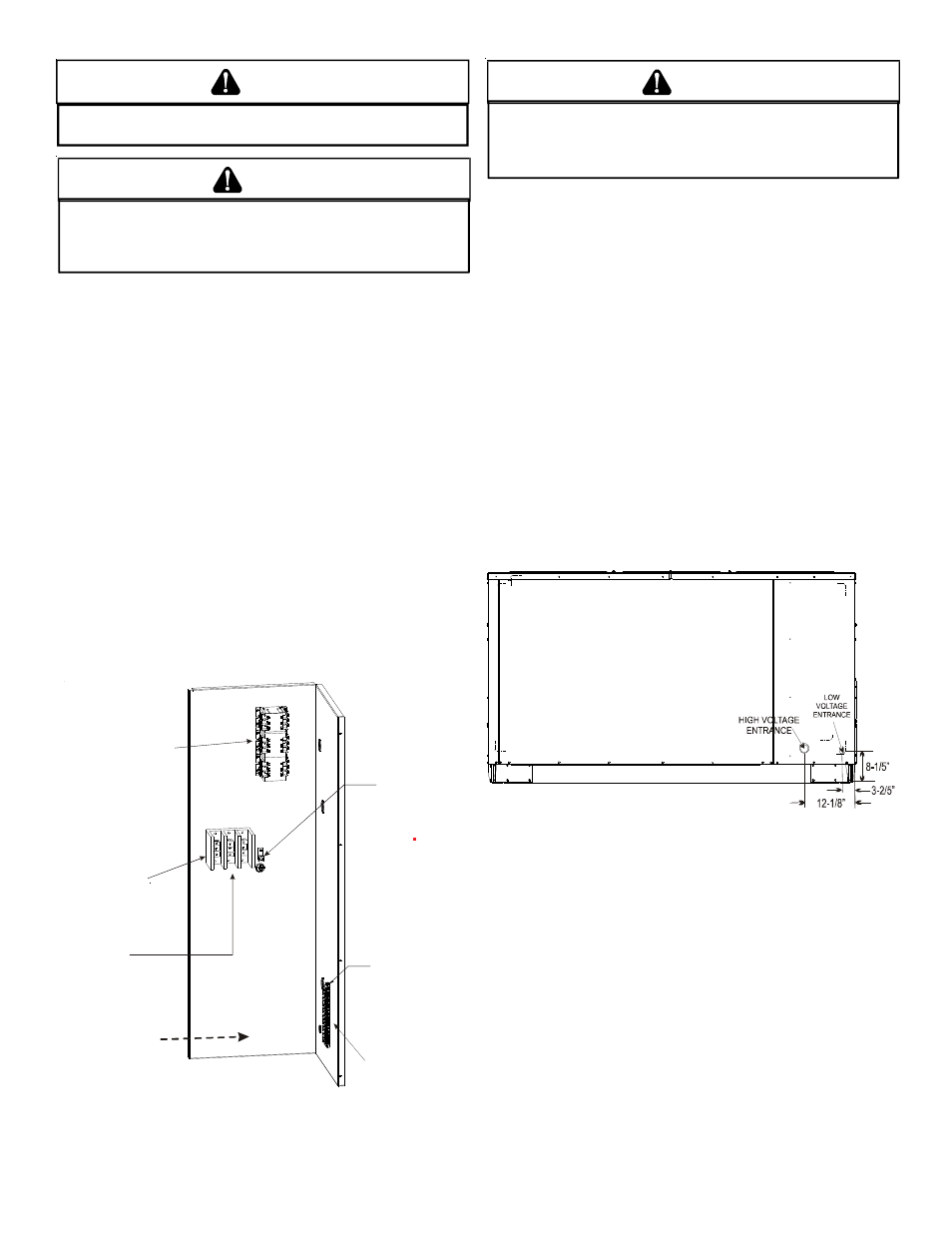
Connect power wiring to the Single Point Power block.
This terminal block is located within the main control
box.
Low Voltage
Terminal Strip
Thermostat wiring
for all units
connect to low
voltage strip
Ground
Lug
Line voltage connects
to power block on
Coolers and the 230v
Gas Packs
Line voltage connects
to middle contactor
on 460v and 575v
Gas Packs
Power Block
(Coolers &
230V Gas Packs
Only)
Field wiring enters
from this direction
POWER AND LOW VOLTAGE BLOCK LOCATIONS
F
AILURE
OF
UNIT
DUE
TO
OPERATION
ON
IMPROPER
LINE
VOLTAGE
OR
WITH
EXCESSIVE
PHASE
UNBALANCE
CONSTITUTES
PRODUCT
ABUSE
AND
WILL
VOID
YOUR
WARRANTY
AND
MAY
CAUSE
SEVERE
DAMAGE
TO
THE
UNIT
ELECTRICAL
COMPONENTS
.
WARNING
Areas Without Convenience Outlet
It is recommended that an independent 115V power source
be brought to the vicinity of the roof top unit for portable lights
and tools used by the service mechanic.
U
NITS
INSTALLED
ON
R
OOF
T
OPS
Main power and low voltage wiring may enter the unit through
the side or through the roof curb. Install conduit connectors
at the desired entrance locations. External connectors must
be weatherproof. All holes in the unit base must be sealed
(including those around conduit nuts) to prevent water leak-
age into building. All required conduit and fittings are to be
field supplied.
Supply voltage to roof top unit must not vary by more than
10% of the value indicated on the unit’s data plate. Phase
voltage unbalance must not exceed 2%. Contact your local
power company for correction of improper voltage or phase
unbalance.
ELECTRICAL ENTRANCE LOCATIONS
Unit is equipped with Single Point Power Block and Low Volt-
age Block.
L
OW
V
OLTAGE
C
ONTROL
W
IRING
1. A 24V thermostat must be installed for unit operation.
It may be purchased with the unit or field -supplied.
Thermostats may be programmable or
electromechanical as required.
2. Locate thermostat or remote sensor in the conditioned
space where it will sense average temperature. Do
not locate the device where it may be directly exposed
to supply air, sunlight or other sources of heat. Follow
installation instructions packaged with the thermostat.