Belt drive b – Goodman Mfg IO-367B User Manual
Page 12
12
System Voltage - That nominal voltage value assigned to a
circuit or system for the purpose of designating its voltage
class.
Nameplate Voltage - That voltage assigned to a piece of
equipment for the purpose of designating its voltage class
and for the purpose of defining the minimum and maximum
voltage at which the equipment will operate.
Utilization Voltage - The voltage of the line terminals of the
equipment at which the equipment must give fully satisfac-
tory performance. Once it is established that supply voltage
will be maintained within the utilization range under all sys-
tem conditions, check and calculate if an unbalanced condi-
tion exists between phases. Calculate percent voltage un-
balance as follows:
Three Phase Models Only
3) PERCENT VOLTAGE
UNBALANCE
2) MAXIMUM VOLTAGE DEVIATIONS
FROM AVERAGE VOLTAGE
1) AVERAGE VOLTAGE
HOW TO USE THE FORMULA:
EXAMPLE: With voltage of 220, 216, and 213
1) Average Voltage = 220+216+213=649 / 3 = 216
2) Maximum Voltage Deviations from Average Voltage = 220 - 216 = 4
3) Percent Voltage Unbalance = 100 x
=
= 1.8%
Percent voltage unbalance MUST NOT exceed 2%
.
4
216
400
216
= 100 X
F
IELD
D
UCT
C
ONNECTIONS
Verify that all duct connections are tight and that there is no
air bypass between supply and return.
F
ILTER
S
ECTION
C
HECK
Remove filter section access panels and check that filters
are properly installed. Note airflow arrows on filter frames.
BELT DRIVE
B
EARING
C
HECK
Prior to energizing any fans, check and make sure that all
setscrews are tight so that bearings are properly secured to
shafts.
For heat pump units, the airflow must be adjusted so that the
air temperature rise falls within the ranges given stated on
Data Plate (see Appendix A - Blower Performance).
NOTE: Section on high static tables may require a field motor
change.
T
ENSION
AND
A
LIGNMENT
A
DJUSTMENT
Correct belt tension is very important to the life of your belt.
Too loose a belt will shorten its life; too tight, premature mo-
tor and bearing failure will occur. Check you belt drive for
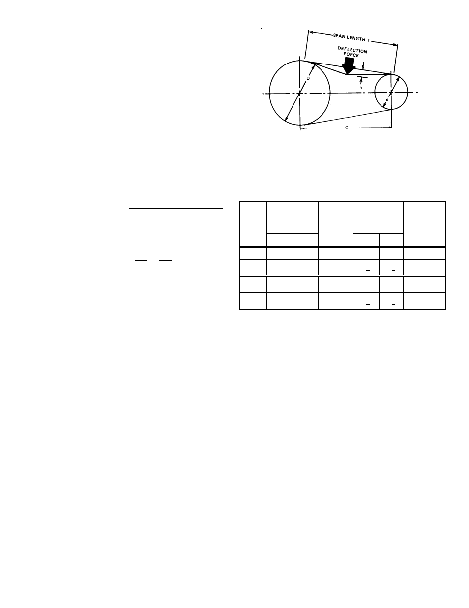
adequate “run-in” belt tension by measuring the force required
to deflect the belt at the midpoint of the span length. Belt
tension force can be measured using a belt tension gauge,
available through most belt drive manufacturers.
t = Span length, inches
C = Center distance, inches
D = Larger sheave diameter, inches
d = Smaller sheave diameter, inches
h = Deflection height, inches
DRIVE BELT TENSION ADJUSTMENT
BELT
DRIVE
Used
New
15 Ton
B, BX Standard
4.3 to 5.5
5.5 + .5 8.2 + .5
1/4 ± 1/16
15 Ton
B, BX
High
Static
4.3 to 5.5
5.5 + .5 8.2 + .5
1/4 ± 1/16
20 Ton
B, BA Standard
4.3 to 5.5
5.5 + .5 8.2 + .5
1/4 ± 1/16
20 Ton
B, BA
High
Static
4.3 to 5.5
5.5 + .5 8.2 + .5
1/4 ± 1/16
MODEL
DEFLECTION
(in)
DEFLECTION
FORCE (lbs)
SHEAVE
DIAMETER
(in)
TYPE
RECOMMENDED POUNDS OF FORCE PER BELT
New V-belts will drop rapidly during the first few hours of use.
Check tension frequently during the first 24 hours of opera-
tion. Tension should fall between the minimum and maximum
force. To determine the deflection distance from a normal
position, measure the distance from sheave to sheave using
a straightedge or a cord. This is your reference line. On mul-
tiple belt drives, an adjacent undeflected belt can be used as
a reference.
E
VAPORATOR
F
AN
R
OTATION
C
HECK
(T
HREE
P
HASE
M
ODELS
O
NLY
)
Check that fan rotates clockwise when viewed from the drive
side of unit and in accordance with rotation arrow shown on
blower housing. If it does not, reverse the two incoming power
cables at Single Point Power Block. In this case, repeat bear-
ing check.
Do not attempt to change load side wiring. Internal wiring
assures all motors and compressors will rotate in correct di-
rection once evaporator fan motor rotation check has been
made.
E
LECTRICAL
I
NPUT
C
HECK
Make preliminary check of evaporator fan ampere draw and
verify that motor nameplate amps are not exceeded. A final
check of amp draw should be made upon completion of air
balancing of the duct system (see Appendix C).