Rigging details, Warning, Caution – Goodman Mfg IO-367B User Manual
Page 7
7
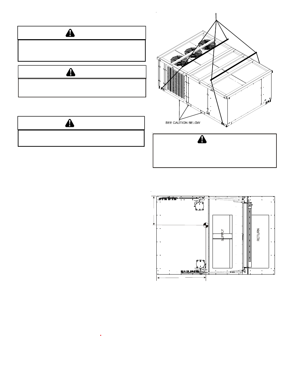
RIGGING DETAILS
WARNING
T
O PREVENT PROPERTY DAMAGE, THE UNIT SHOULD REMAIN IN AN UPRIGHT
POSITION DURING ALL RIGGING AND MOVING OPERATIONS.
T
O FACILITATE
LIFTING AND MOVING WHEN A CRANE IS USED, PLACE THE UNIT IN AN
ADEQUATE CABLE SLING.
D
O
NOT
LIFT
UNITS
TWO
AT
A
TIME
. P
ROVISIONS
FOR
FORKS
HAVE
BEEN
INCLUDED
IN
THE
UNIT
BASE
FRAME
. M
INIMUM
FORK
LENGTH
IS
72”
TO
PREVENT
DAMAGE
TO
THE
UNIT
.
CAUTION
Provisions for forks have been included in the unit base frame.
No other fork locations are approved.
WARNING
T
O PREVENT POSSIBLE EQUIPMENT DAMAGE, PROPERTY DAMAGE, PERSONAL
INJURY OR DEATH, THE FOLLOWING BULLET POINTS MUST BE OBSERVED
WHEN INSTALLING THE UNIT.
•
Unit must be lifted by the four lifting holes located at
the base frame corners.
•
Lifting cables should be attached to the unit with
shackles.
•
The distance between the crane hook and the top of
the unit must not be less than 60”.
•
Two spreader bars must span over the unit to prevent
damage to the cabinet by the lift cables. Spreader
bars must be of sufficient length so that cables do not
come in contact with the unit during transport.
Remove wood struts mounted beneath unit base
frame before setting unit on roof curb. These struts
are intended to protect unit base frame from fork lift
damage. Removal is accomplished by extracting the
sheet metal retainers and pulling the struts through
the base of the unit. Refer to rigging label on the unit.
Important: If using bottom discharge with roof curb, duct-
work should be attached to the curb prior to installing the
unit. Ductwork dimensions are shown in Roof Curb Installa-
tion Instructions.
Refer to the Roof Curb Installation Instructions for proper curb
installation. Curbing must be installed in compliance with the
National Roofing Contractors Association Manual.
Lower unit carefully onto roof mounting curb. While rigging
unit, center of gravity will cause condenser end to be lower
than supply air end.
W
HEN
UNIT
IS
SUSPENDED
,
BOARDS
AND
SHIPPING
BRACE
WILL
DROP
WHEN
SCREWS
ARE
REMOVED
. T
O
PREVENT
PERSONAL
INJURY
, STAND CLEAR.
R
EMOVE
FORK
HOLE
BRACKETS
,
BOARDS
AND
SHIPPING
BRACE
FROM
BOTTOM
OF
UNIT
BEFORE
PLACING
UNIT
ONTO
CURB
.
CAUTION
To assist in determining rigging requirements, unit weights
are shown as follows:
COMPRESSOR 1
COMPRESSOR 2
CG
E
V
A
P
O
R
A
T
O
R
C
O
IL
S
A
B
C
X
D
Y
CORNER & CENTER OF GRAVITY LOCATIONS