Ystem, Nstallation – GTO SL-1000B User Manual
Page 35
33
D
UAL
G
ATE
S
YSTEM
I
NSTALLATION
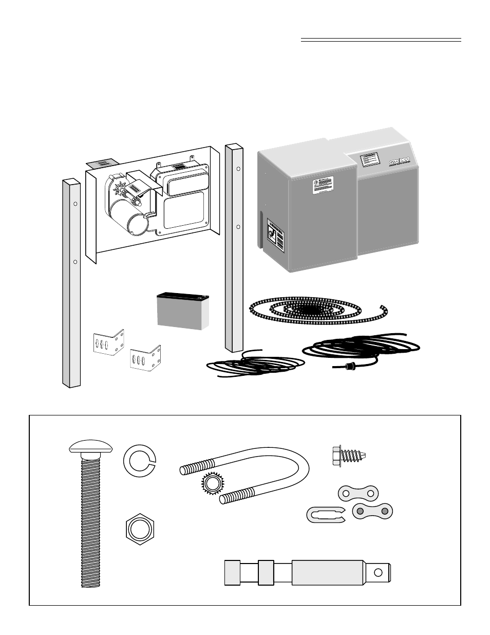
(2) Chain Brackets
Operator Housing
32’ Drive Chain
Second Gate Operator
(2) 2” square x 48” long le
gs
60’ Power Cable
w/ Strain Relief
Install the second gate operator in the same manner as the Single gate operator starting on page 14 of this
manual. The second gate preparation and wiring of the second (auxiliary) operator follow on the next two
pages. Once the second gate operator is installed, Set the DIP switches for DUAL gates and the order in
which the gates open (“sequencing”). Setting the Control Board for Dual Gate Installations begins on
page 37.
S
ECOND
G
ATE
(A
UXILIARY
) O
PERATOR
P
ARTS
& H
ARDWARE
Battery Cable
Battery
The SL-2200 comes with
a battery and control box
the SL-1200 does not.
(4)
3
/
8
”-
16 x 2” diameter U-Bolts and
(8)
3
/
8
”
Serrated Nuts (RB210)
(2) Quick Release Pins (211IH)
(2) Chain Master Links
(RB208)
(4)
1
/
4
”
-20 x
1
/
2
”
Screws
(RB226)
(4)
3
/
8
”
-16 x 3
”
Carriage Bolts (RB659)
(4)
3
/
8
”
Nuts
(RB668)
(4)
3
/
8
”
Lock Washers
(RB641)