Gto t, Nstallation, Ransformer – GTO SL-1000B User Manual
Page 20: Strip
18
S
TEP
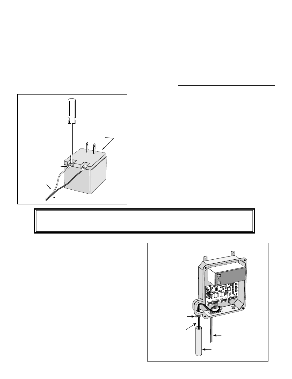
11:
Feed the low voltage wires upward through the
strain relief on the bottom of the control box
(see Illustration J). Pull 6” to 8” of wire into the
control box.
If accessories (i.e. safety loops, card readers, etc.)
are to be added during this installation, do not
tighten the strain relief screw against the wires
until the accessories have been connected. When
all accessories have been connected, fully tighten
the strain relief screw against the wires.
I
NSTALLATION
OF
THE
GTO T
RANSFORMER
C
ONT
.
S
TEP
10:
Strip
3
/
16
” off the ends of the low voltage wire
and attach ends to the transformer terminals;
red wire to [RED], black wire to [BLK], (see
Illustration I
). A dab of household petroleum
jelly on each terminal will help prevent
corrosion.
We recommend crimping a spade-tongue
terminal (not provided) to the end of each wire
before attaching it to the transformer.
To prevent damage to transformer, make
sure the exposed wire ends do not touch
each other!
Transformer
Red
Spade Tongue
terminal
Black
DO NOT plug the transformer into outlet.
The transformer will be plugged in during STEP 13.
Illustration I
NOTE: Wires coming from the ground to the control
box should be run through PVC conduit to protect
them from lawn mowers, weed eaters and grazing
animals (see illustrations on page 13).
Illustration J
S
TEP
9
Run the low voltage wire from the electrical outlet to the control box. Do not exceed 1000’.
NOTE: Pull approximately 1 foot of extra low voltage wire into the control box to accommodate terminal connections.
To maintain adequate charging power, use appropriate gauge, stranded, direct burial wire (see Accessory Catalog).
Do not use telephone wire or any solid core wire because it will not provide adequate current. Never splice
wires together.
R
E
D
B
LK
O
R
G
B
LU
G
R
N
C
LS
E
D
G
O
P
N
E
D
G
R
E
D
G
R
N
O
R
G
B
LU
W
H
T
B
LK
O
R
G
B
LU
G
R
N
C
LS
E
D
G
O
P
N
E
D
G
LEARN
AUTO
CLOSE
INERTIA
STATUS
BATT
+
–
OBSTRUCT
SENS.
RCVR
R G B
ALARM
SECOND OPE
RATOR
FIRST OPERA
TOR
POWER IN
18VAC S
OLAR
~ ~
– +
ACCES
SORY
PWR. SW
.
Operator Power Cable
PVC Conduit
Strain Relief Screw
Low Voltage Wire
from AC Transformer