Be d f, Notice – Grizzly G0516 User Manual
Page 29
G0516 Lathe/Mill
-27-
0.005" 0.010"
C B
D E
F
35 80
90 30
100
50 80
66 30
100
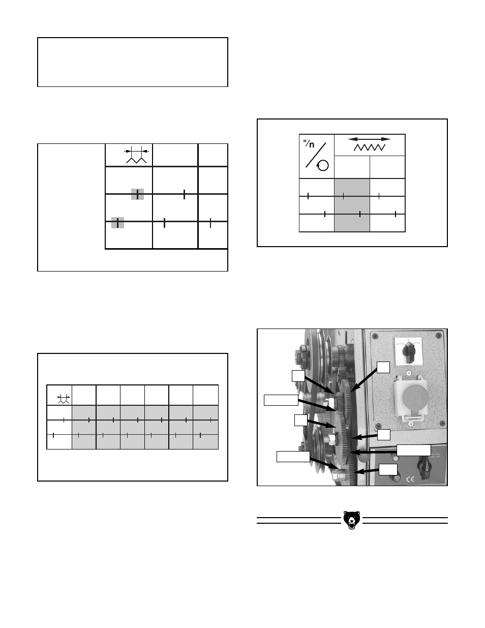
Figure 34. Chart showing gear setup for .005".
Figure 35. Actual gear setup for .005" feed rate.
Figure 35 shows a profile of the .005" feed rate
actual gear setup on the machine. Notice how the
gears mesh together in the locations displayed on
the chart.
Here is a real-world example of a gear setup
as shown on the chart:
When the lathe/mill is shipped from the factory, it
is geared for a carriage feed rate of .005" per
spindle revolution, or the gear combination shad-
ed in
Figure 34.
⁄
n
16
18
B
E
D
F
70
40
60
80
7
8
60
45
Figure 32. The shaded boxes highlight the gear
mesh lines.
1"
⁄
n
16
18
20
24
32
40
B
E
D
F
70
40
60
80
70
80
60
45
70
80
60
50
70
40
50
100
70
80
45
60
70
40
30
100
Figure 33. The shaded boxes show specific
gear setups.
6.
The boxes shaded in
Figure 33 represent
the actual gear combinations required to cut
the thread pitches.
5.
The lines between gears “B” & “E” and gears
“D” & “F” on the chart in
Figure 32 indicate
where the gears should be in mesh.
NOTICE
On some setups, smaller gears must be
used as spacers on the adjustable shafts.
35
80
90
30
100
Spacer
In Mesh
In Mesh