Ir remote, 4x4 component matrix over cat-5 receiver, Rmt-4ir remote control configuration – Gefen EXT-COMPAUD-CAT5-444 User Manual
Page 20
17
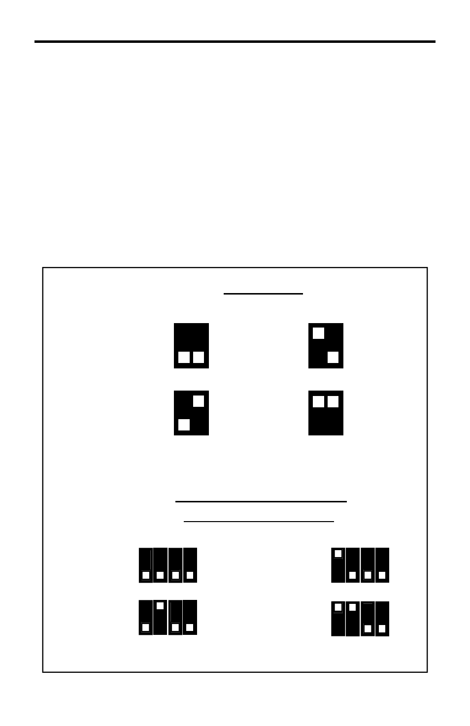
RMT-4IR REMOTE CONTROL CONFIGURATION
IR Remote
Remote Channel 1:
Default
1 2
Remote Channel 2:
1 2
Remote Channel 3:
1 2
Remote Channel 4:
1 2
How to Resolve IR Code Confl icts on the Receiver
In the event that IR commands from other remote controls confl ict with the
supplied RMT-4IR remote control, changing the remote channel will alleviate this
issue. The RMT-4IR remote control and the 4x4 Component Matrix Over CAT-5
receiver have DIP SWITCHES for confi guring the remote channel that both units
use to communicate. These settings must match each other for proper operation.
The 2 DIP SWITCH bank on the RMT-4IR is located underneath the battery
cover (please see page 14 for a picture). The 4 DIP SWITCH bank for the 4x4
Component Matrix Over CAT-5 receiver is located on the underside of the unit
beneath a black piece of metallic tape. DIP SWITCH 1 and 2 on the RMT-4IR
correspond to *DIP SWITCH 1 and 2 on the 4x4 Component Matrix Over CAT-5
receiver.
NOTE: *DIP SWITCHES 3 and 4 are not used on the 4x4 Component Matrix
Over CAT-5 receiver.
4x4 Component Matrix
Over CAT-5 receiver
Remote Channel 1:
Default
Remote Channel 4:
1
1
2
2
3
3
4
4
Remote Channel 3:
1 2 3 4
Remote Channel 2:
1 2 3 4