Caution, Installation – GSI Outdoors PNEG-1153 User Manual
Page 9
PNEG-1153 CALC-U-DRI Moisture/Matic/Manager
9
4. INSTALLATION
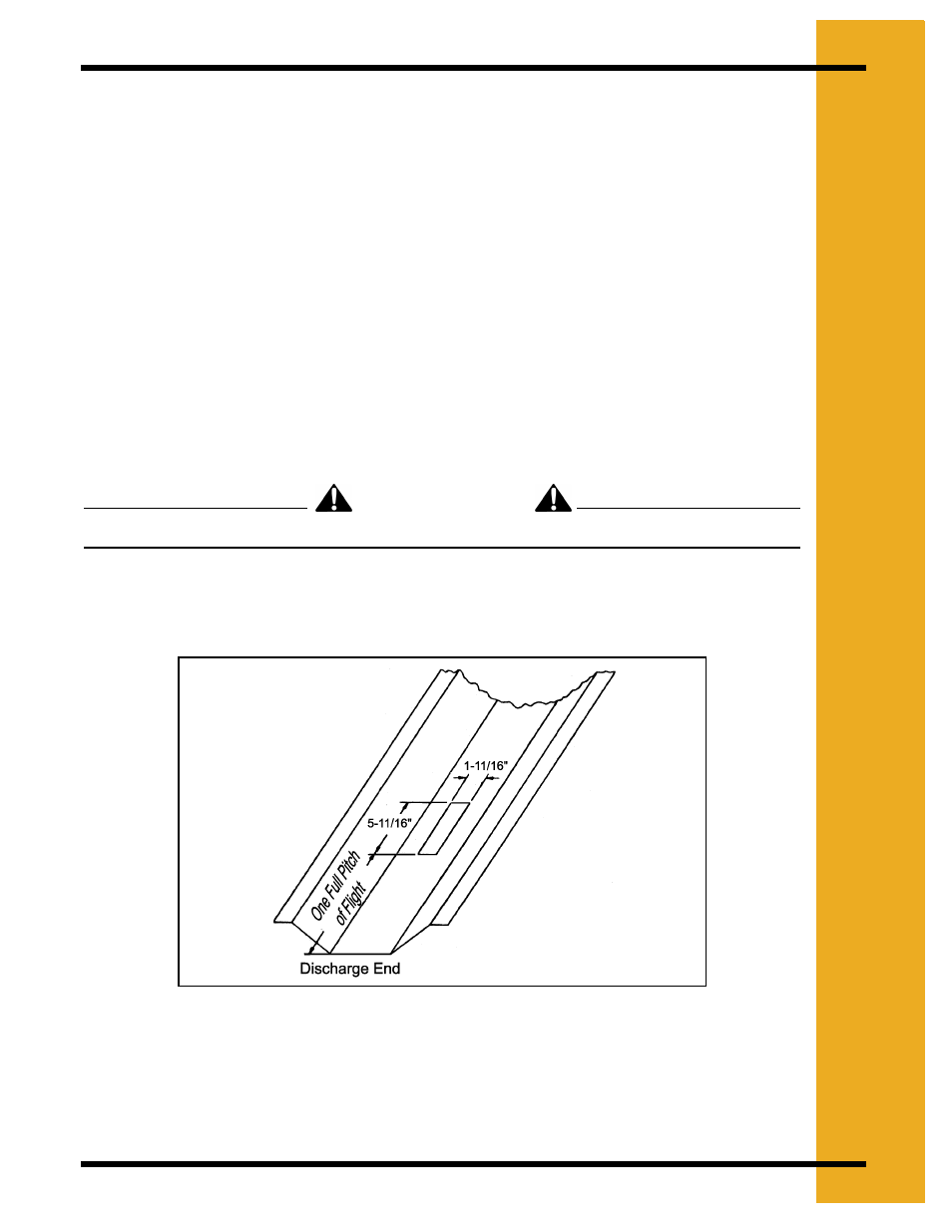
2. Position the sensor connecting band on the discharge tube so that the rectangular hole is
toward the discharge end. Mark the outline of the rectangular hole and the edges of the
band on the discharge auger tube. Cut a hole in the discharge tube eight (8)" long so the
outline of the rectangular hole is removed (stay inside the total overall length marks of the
band). Cut up one side of the discharge tube about one third (1/3) of the way around the
tube. This extra room is for ease of removing flighting in the next step.
3. Replace the connecting band on the discharge tube in the same position as in
(above) and mark the flighting at each end of the rectangular hole. Weld the discharge
auger flighting to the shaft 3/8" beyond each of the marks. After the flight is welded at these
points, cut out six and one half (6-1/2)" of the flighting all the way to the center shaft.
4. Smooth all the rough edges from the cut area and position the sensor hole centered over
the six and one half (6-1/2)" area, then tighten the connecting band.
5. Before installing the sensor, see Sensor Installation
.
Sensor Cut-Out for Flat Bottom Discharge Units
DISCONNECT POWER TO THE AUGER MOTOR BEFORE PROCEEDING ANY FURTHER!
1. Determine where the sensor can be located.
There must be at least one
full pitch of flight before and after the sensor.
Figure 4D
CAUTION