See figure 4e), Installation – GSI Outdoors PNEG-1153 User Manual
Page 10
10
PNEG-1153 CALC-U-DRI Moisture/Matic/Manager
4. INSTALLATION
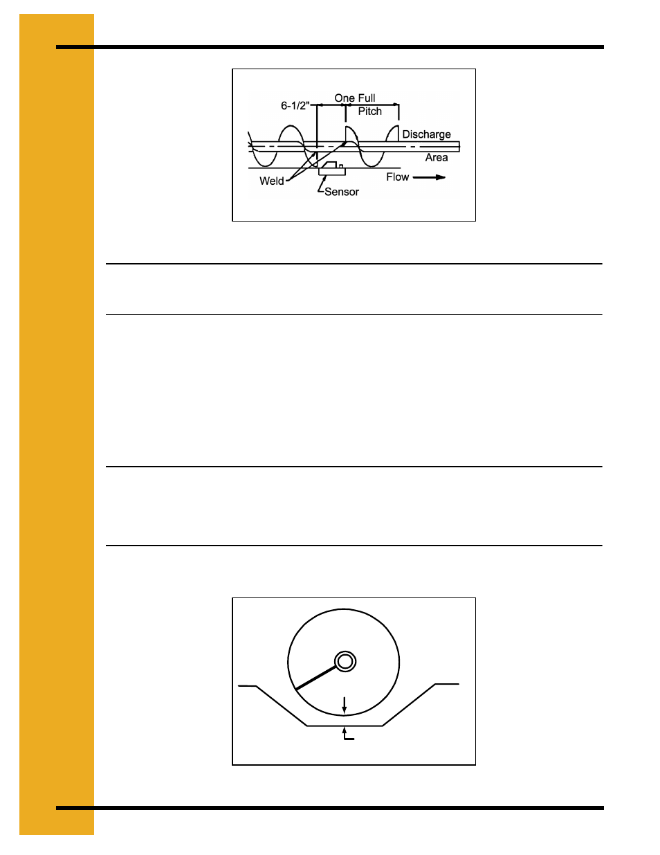
Figure 4E
Note: If there is more than 5/8" gap between the bottom pan and the outer edge of the
flighting, do not use a sensor in that location. Use another location, such as a
take-away auger.
2. Remove the flat bottom pan and mark the sensor cutout area at least one (1) pitch length
of the auger from the discharge area. This allows for good pickup of the grain when it leaves
the sensing area. Cut the sensor rectangle 1-11/16" x 5-11/16" with a saber saw (do not
torch cut) and check so the sensor block fits into it with the stepped edge.
3. Hold the pan up to the unit and mark the flighting where the sensor hole is located. Remove
the pan and mark the flighting about 3/8" away from marks just made, so the new marks
are six and one half (6-1/2)" apart.
Note: For seven (7)" flight or less, cut the flight to the shaft. Weld the auger flight to the
shaft at each end of the six and one half (6-1/2)" cutout marks, then cut out the six
and one half (6-1/2)" of flighting from the auger, leaving only the drive tube. For eight
(8)" or larger diameter flighting, one-half (1/2)" of flighting can be left as a ribbon
around the shaft in the cutout area.
4. Smooth all the rough edges from the cutout area.
Figure 4F
5/8" Max. Clearance
(Do not use if over 5/8")