Installation – GSI Outdoors PNEG-1153 User Manual
Page 16
16
PNEG-1153 CALC-U-DRI Moisture/Matic/Manager
4. INSTALLATION
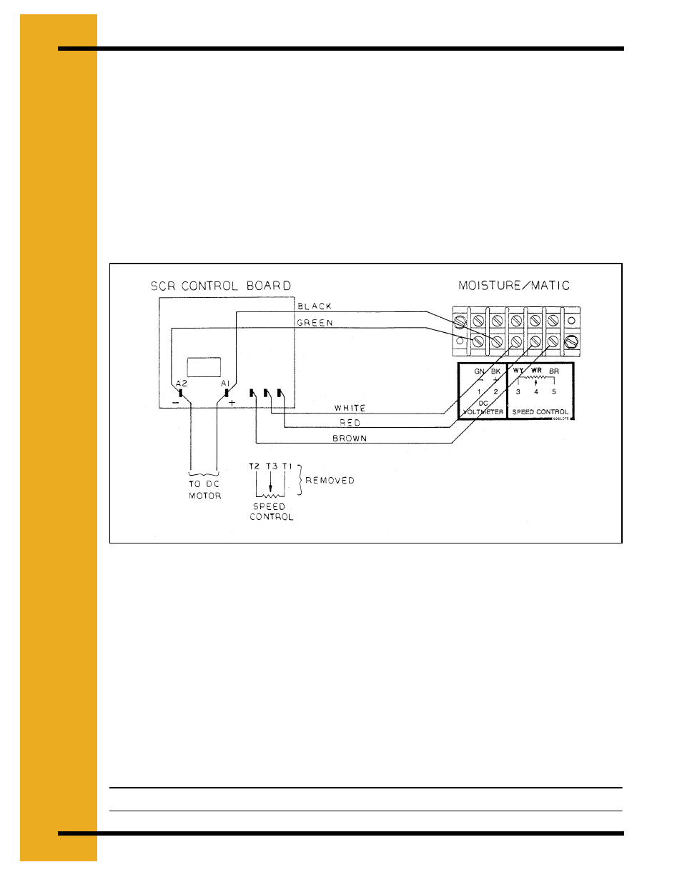
b. In the Moisture/Matic control box, locate the five (5) post terminal. This has “DC
Voltmeter” written on it. The green wire should be placed on terminal one (1) and the
black on terminal two (2).
3. Speed Control Hook-Up: Locate the three (3) leads on the SCR control board (in the dryer
control box) that are attached to the speed control potentiometer.
a. Mark down the wire color and terminal as you remove the three leads. This can be used
for a test if problems should appear.
b. Determine the center lead from the speed control potentiometer. (This may not be the
center lead on the SCR board). Remove this wire from the SCR board and replace it
with the red wire in the five (5) conductor cable from the Moisture/Matic.
Figure 4P
c. Attach the other end of this red wire to terminal four (4) as marked by the decal on the
back panel in the Moisture/Matic.
d. Determine which wire is attached to the “slow” end of the speed control potentiometer.
Remove this wire from the SCR board and replace it with the white wire from the
Moisture/Matic.
e. Attach the other end of this white wire to terminal three (3) on the back panel of the
Moisture/Matic.
f. Remove the remaining wire from the SCR board and replace it with the brown wire from
the Moisture/Matic. Attach the other end of this wire to terminal five (5) on the back
panel of the Moisture/Matic.
Note: See Appendix B for more examples on wiring.
F
A
S
T
S
L
O
W