Grizzly G0528 User Manual
Page 18
-16-
model g0528 (mfg. 5/04+)
figure 13. installed hold-down assemblies.
Workpiece hold-
down assemblies
threaded
Star Knobs
DO NOT operate the Model G0528 without an
adequate dust collection system. This saw
creates substantial amounts of wood dust
while operating. failure to use a dust collec-
tion system can result in short and long-term
respiratory illness.
13. verify fence face alignment shown in figure
12 using a straightedge. if the fence faces are
out of alignment when fully retracted into their
housings, loosen the fence housing lock nuts
and slide the fence face back into alignment.
14. remove one of the hex nuts from each of the
hold-down brackets.
15. Slide the hold-down brackets through the
mounting holes on the dust cover and secure
them from the underside of the dust cover
with the hex nuts removed in
Step 14.
16. tighten the hex nuts until the hold-down
brackets are secure.
17. Secure the hold-down fingers to the hold-
down brackets by tightening the threaded
star knob (
figure 13).
Note: Do not worry about precise placement
of the hold-down brackets or fingers at this
time.
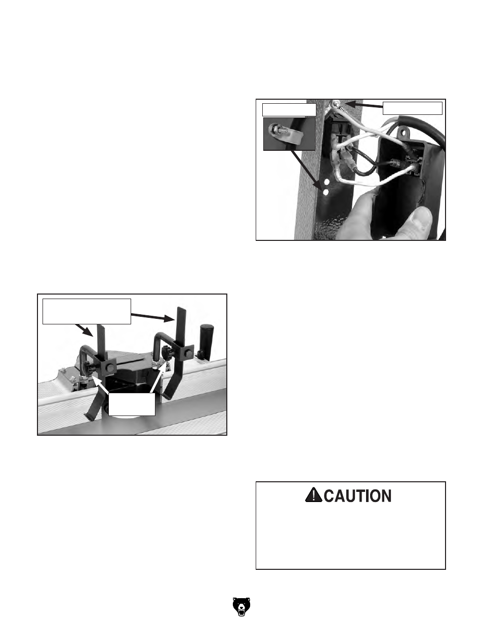
20. Secure the green ground wires to the ground
screw (
figure 14) from the power cord, and
attach the switch box to the stand leg, using
the phillips head screw and hex nut already
installed in the frame.
21. push the switch through the cut-out on the
stand leg, and plug-in the black and white
power wires to the back of the switch, refer
to wiring diagram on
page 27 for connection
locations.
22. place the loom clamp around the power
cord and mount it in the lower mounting hole
(
figure 14) using the #10-24 x
3
⁄
4
" phillips
head screw, #10 flat washer, and #10-24
nut.
23. Secure the switch box to the back of the
switch using the remaining phillips head
screws, the external toothed washers, and
the hex nuts already installed in the frame.
24. Fit a 2
1
⁄
2
" dust collection hose over the
dust port and secure it in place with a hose
clamp.
figure 14. Switch installation.
loom Clamp
ground Screw
18. install the strain relief on the outside of the
switch, using the plastic nut from the inside
to secure the strain relief to the switch box.
19. Feed the power wires through the strain relief
and tighten the strain relief screw against the
main cord jacket.