Installation, Warning, Check the electrical grounding – Graco Inc. 308287 User Manual
Page 5
5
308–287
Installation
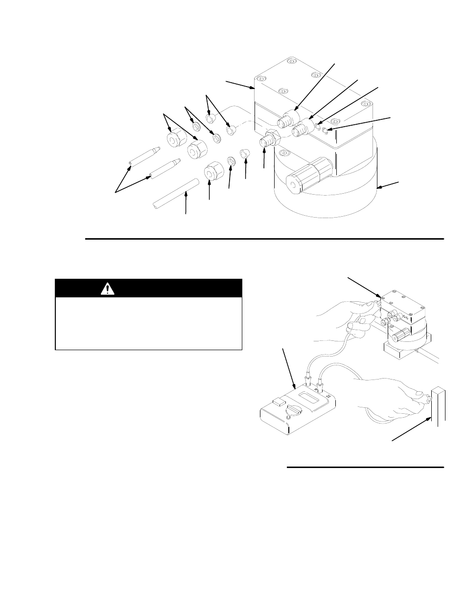
Fig. 1
KEY
A
Tubing, 1/4” OD
B
Nut (nylon)
C
Ferrule, back (nylon)
D
Ferrule, front (nylon)
E
Air Inlet Fitting
F
Electrical Chassis
G
Fiber Optic Cables
H
Gear Housing Assy.
J
Nut (aluminum)
K
Ferrule, back (aluminum)
L
Ferrule, front (aluminum)
J
A
C
D
E
F
H
G
Flow Indicator
Light
(Green)
Power Indicator
Light
(Yellow)
Fiber Optic
Sender 1
Fiber Optic
Sender 2
K
L
B
01849
Check the Electrical Grounding
WARNING
Proper electrical grounding of your system is
essential when used with flammable or combustible
liquids. For you safety, read the warning section
FIRE, EXPLOSION, AND ELECTRIC SHOCK
HAZARD on page 2.
Have a qualified electrician check the electrical
grounding continuity between the flow meter electrical
chassis and a true earth ground as shown in Fig. 2. If
the resistance is greater than 25 ohms, check the
mounting or add a ground strap to the chassis.
Fig. 2
True Earth Ground
Digital
Voltage
Meter
Electrical
Chassis
01850