0 i0, Chapter 7, Rogramming – GE EPM 3000P User Manual
Page 27: Roup, Lobal, Eter, Etup, 1: group 0 p, 0, f, 0 - t
CHAPTER 7
P
ROGRAMMING
G
ROUP
0: G
LOBAL
M
ETER
S
ETUP
The Global Meter Setup includes Functions 0 through 5 that control configuration and basic operation. Below is an
outline of GROUP 0 to assist in locating a feature. FUNCTION 3 System Configuration contains Switch PACKS with
various options, including open delta installation and communications.
T
ABLE
7-1: GROUP 0 P
ROGRAMMING
F
ORMAT
FUNCTION NUMBER
FUNCTION
0. Integration
Interval
1.
Meter Address for Communication
2.
Baud Rate for Communication
3. System
Configuration
4.
Relay 1 Set-up/Time Delay
5.
Relay 2 Set-up/Time Delay
E.
Exit Programming GROUP 0
7.1 G
ROUP
0, F
UNCTION
0 - T
HE
I
NTEGRATION
I
NTERVAL
INTEGRATION INTERVAL: The time over which all instantaneous readings are averaged to obtain a maximum and
minimum demand. The Integration Interval is entered in seconds. When entering 15 minutes, enter: 0900 seconds.
Ö
To change the INTEGRATION INTERVAL, follow these steps:
NOTE: PRESS MAX/MIN/LIMITS, AT ANY TIME, TO CANCEL BEFORE STORING THE LAST DIGIT OR SWITCH.
MAX
AC VOLTS
A B C N
AC AMPS
MAX/MIN
LIMITS
VOLTS
PRINT
PROG
PHASE
NEXT
0.
AMPS
B C A
I I I
A B C
N N N
I I I
A B C
LM2
LM1
MIN
MAX
AC VOLTS
A B C N
AC AMPS
MAX/MIN
LIMITS
VOLTS
PRINT
PROG
PHASE
NEXT
00.
AMPS
B C A
I I I
A B C
N N N
I I I
A B C
LM2
LM1
MIN
0 I0
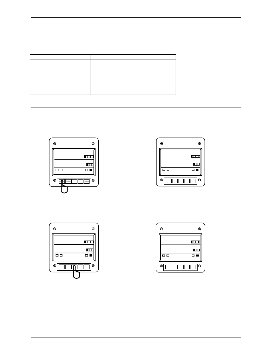
Step 1:
a. Enter Group Level of Programming Mode,
(see Chapter 6).
b. Press MAX/MIN/LIMITS until 0. appears in upper
display.
c. Press VOLTS to activate the GROUP.
Ö
00. appears in upper display, indicating current Group
and Function number.
Ö
Lower display indicates current Interval setting.
MAX
AC VOLTS
A B C N
AC AMPS
MAX/MIN
LIMITS
VOLTS
PRINT
PROG
PHASE
NEXT
00
AMPS
B C A
I I I
A B C
N N N
I I I
A B C
LM2
LM1
MIN
3 _ _
MAX
AC VOLTS
A B C N
AC AMPS
MAX/MIN
LIMITS
VOLTS
PRINT
PROG
PHASE
NEXT
00.
AMPS
B C A
I I I
A B C
N N N
I I I
A B C
LM2
LM1
MIN
300
Step 2:
a. Press VOLTS to begin Data Entry Sequence.
Ö
Three dashes appear in lower display.
b. Press PRINT/PROG for desired number.
Press PRINT/PROG once and the blank signifies zero.
Press PRINT/PROG twice and 1 appears.
c. Press VOLTS to store.
Ö
Repeat this procedure until new Integration Interval is
entered.
Ö
When complete, lower display indicates new
Integration Interval.
See Chapter 12 to Exit.
GE Industrial Systems
22