265 volt sub-base and direct connected units – GE Monogram 5800 Series User Manual
Page 42
42
Power Connection for 2900, 900
and 5800 Series Zonelines
All 2900, 900, and 5800 Series Zonelines are equipped with
universal heaters allowing chassis installation flexibility. The
Zoneline
®
units are connected to the building power supply
by a unique power connection kit. By utilizing a separate
universal power connection (UPC) kit, each unit is capable of
providing various outputs of electric resistance heat to more
closely meet the heating requirements of the particular room,
thereby increasing the installation flexibility of the particular
chassis. This power connection kit is the only means of
supplying power to the Zoneline chassis. The appropriate
kit is determined by the voltage, the means of electrical
connection, either line cord connected or permanently
connected, and the desired resistance heat output that
may be supported by the branch circuit.
230/208-Volt Line-Cord Connected Units
Line Cord Kits consist of a self-aligning nine-pin molded
connector that plugs into a mating connector on the Zoneline
chassis and insulated line cord with an electrical plug on
the end. The configuration of the electrical plug conforms
to NEC standards for the circuit amperage and the position
of the wires in the nine-pin connector determines the heater
wattage and current requirements when it is plugged into
the Zoneline chassis.
The power connection kit is selected by the amperage of
the circuit where it will be installed. Each line cord kit has an
integral Leakage Current Detection and Interruption (LCDI) or
Arc Fault Current Interrupter (AFCI) device as required by the
National Electrical Code (NEC) and Underwriters Laboratory
(UL) for line-cord connected air conditioners manufactured
on or after August 1, 2004. The line-cord power connection
kits are shown in the table below.
230/208-Volt Line-Cord Connected Units
Line Cord
Kit
Electric
Heat
BTUH
Electric
Heater
Watts
Electric
Heat
Amps
Min. Circuit
Protection
(Amps)
RAK15
8600/7100
2550/2090
11.6/10.6
15
RAK20
11700/9600
450/2820
15.5/14.2
20
RAK0
17000/1900
5000/4090
22.4/20.4
0
Electric Heat Amps include electric heater and fan motor current draw.
230/208-Volt — Permanently Connected Units
Permanently connected units do not require the LCDI or AFCI
device. Permanent connection is usually made through the
use of a sub-base. Each 20/208-volt sub-base consists of
a sub-base with appropriate receptacle for minimum circuit
amperage, a chaseway to route power connector from the
sub-base to the chassis, wiring to connect the sub-base
to building wiring and a short-line cord with a self-aligning
nine-pin connector to connect to chassis and plug into the
receptacle in the sub-base. Permanent, or direct wired,
installation of a 20/208-volt unit requires a junction box kit,
RAK4002A, which attaches to the chassis to form an enclosed
junction box.
The short sub-base line cord may not be used without the
sub-base.
For 2900 and 900 Series 20/208-volt units where a
permanent installation using flexible conduit is desired, the
RAK4002A forms an enclosed junction box on the chassis.
The RAK4002A has a 7/8" diameter hole to allow conduit to
be connected to the junction box. For direct connection,
purchase and install the appropriate Universal Power Supply
Kit (also referred to as the Direct Connection Kit below) that
matches the ampacity of the building circuit connected to
the unit. This nine pin connector with three 7" long conductor
wires is used for direct connections to the building wiring
inside a direct connect junction box. These wires are then
connected to the building wiring by field-supplied connectors.
For 5800 Series 20/208-volt units, the permanent installation
using flexible conduit procedure is the same as for the 2800
and 800 Series units, except the junction box kit is RAK4002B.
Electric Heat Amps include electric heater and fan motor current draw.
Each 265-volt sub-base kit consists of a sub-base with appropriate receptacle for minimum circuit
amperage, a chaseway to route the power connector from the sub-base to the chassis and wiring
to connect the sub-base to the building wiring.
The 265-volt power connection kit must be ordered separately.
All wiring must conform to local electrical regulations
and codes.
265 Volt Sub-Base and Direct Connected Units
Sub-Base
Power
Connection
Kit
Direct
Connection
Kit
Electric
Heat
BTUH
Electric
Heater
Watts
Electric
Heat
Amps
Min. Circuit
Protection
(Amps)
RAK204E15
RAK5172
RAK5157
8600
2550
10.
15
RAK204E20
RAK5202
RAK5207
11700
450
1.8
20
RAK204E0
RAK502
RAK507
17000
5000
19.6
0
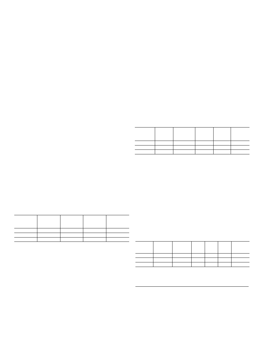
230/208 Volt Sub-Base and Direct Connected Units
Sub-Base
Direct
Connection
Kit
Electric
Heat
BTUH
Electric
Heater
Watts
Electric
Heat
Amps
Min. Circuit
Protection
(Amps)
RAK204D15P
RAK4157
8600/7100
2550/2090
11.6/10.6
15
RAK204D20P
RAK4207
11700/9600
450/2820
15.5/14.2
20
RAK204D0P
RAK407
17000/1900 5000/4090
22.4/20.4
0
Electric Heat Amps include electric heater and fan motor current draw.
265- or 277-Volt Unit Installation — Permanently
Connected Units
National Electric Code (Article 440 Section G) requires
permanent connection for units connected to power sources
over 250 volts; therefore these units must be permanently
connected (direct wired) with field-supplied connectors.
Units connected using a sub-base meet the requirement
for permanent connection since all wiring is internal wiring
between the sub-base and the chassis.
Since 265-volt units may not be line cord connected, an LCDI
device is not required.