Auxiliary control switches, Cooling temperature limits, Heating temperature limits – GE Monogram 5800 Series User Manual
Page 12
12
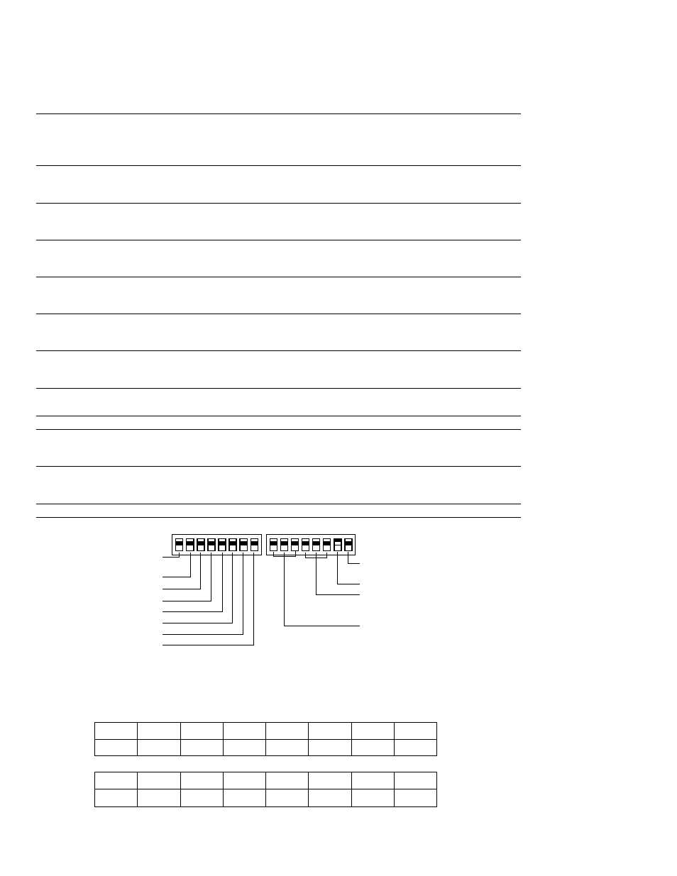
Auxiliary Control Switches
These switches are located behind the room cabinet under the control panel.
2900 and 3900 Series
Switches
Description
Left Switches
(1)
ALL I2R
Heat pump override —
Down — Normal heat pump operation
Up — resistance heat only (900 Series only)
(2)
C: FAN
Fan control for cooling operation —
Down — Fan Continuous
Up — Fan Cycle
()
H: FAN
Fan control for heating operation —
Down — Fan Cycle
Up — Fan Continuous
(4)
CLASS 2
Remote Thermostat Mode —
Down — Unit Control
Up — Remote Thermostat
(5)
LOAD SHED
Load Shedding when connected to Central Desk Control System —
Down — Fan shuts off with unit
Up — Fan under “Smart Fan” settings
(6)
FREEZ S
Freeze Sentinel
™
Override —
Down — Freeze Sentinel ON
Up — Freeze Sentinel OFF
(7)
CONST FAN
Constant Fan —
Down — Fan runs normally
Up — Fan runs when unit is in STOP position
Right Switches
TL1 – TL
Cooling temperature limiting (See table at bottom of page)
TL4 – TL6
Heating temperature limiting (See table at bottom of page)
(7)
Heat Sentinel switch —
Down — Heat Sentinel OFF
Up — Heat Sentinel ON
(8)
Heat Boost (900 series only) —
Down — Heat Boost OFF
Up — Heat Boost ON
Auxiliary (2900 and 900 series)
HIGH
COOL
1
2
3
4
5
6
1
2
3
4
5
6
7
8
UP
DOWN
UP
DOWN
ALLI
2
R (All Electric Heat)
(3900 Series models only)
C: FAN CN (Cooling–Smart Fan)
H: FAN CY (Heating–Smart Fan)
CLASS 2 (Remote Thermostat)
LOAD SHEDDING (CDC)
FREEZ Sen (Freeze Sentinel)
CONST FAN (Constant ON Fan)
NO FUNCTION (Reserved for future use)
TL1 (H) (Temp. Limit 1–Heat)
TL2 (H) (Temp. Limit 2–Heat)
TL3 (H) (Temp. Limit 3–Heat)
TL1 (C) (Temp. Limit 1–Cool)
TL2 (C) (Temp. Limit 2–Cool)
TL3 (C) (Temp. Limit 3–Cool)
7
8
Heat Sentinel
HEAT BOOST
(3900 Series models only)
Cooling and Heating temperature limits are set independently, temperature limiting
switches are in factory-set down position, except as noted.
Cooling Temperature Limits
Switches Up
NONE
1
1, 2
2
2,
1, 2,
1,
60
64
66
68
70
72
74
76
Heating Temperature Limits
Switches Up
6
4, 6
4, 5, 6
5, 6
5
4, 5
4
NONE
65
70
72
74
76
78
80
85
900 Series shown