Act20 pin pad installation diagram, Op tio na l e xit re ad er en try re ad er, Controller – Guardian Technologies ACT1000 User Manual
Page 27: Controller cable act20
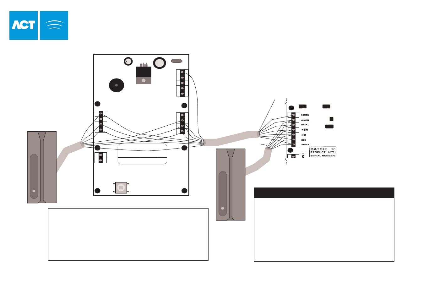
Cable: 8 Core Screened,
Max 30m
Controller
EN
TR
Y/E
XIT
R
EA
DE
R
0 1 2 3 4 5 6 7 8 9
BATCH:
PRODUCT:
SERIAL NUMBER:
98XX-1
ACT20 REV2.1
012345
OP2
OP3
BUZZER
0V
0V
DOOR
CONTACT
PUSH
BUTTON
INTERLOCK
(PB2)
T
A
M
P
E
R
12
-2
4V
A
C
/D
C
+
-
WHI
TE
GRE
EN
BLU
E
BROW
N
YELLO
W
BLA
CK
RED
O
RA
N
G
E
SENSE
UNUSED
OP
TIO
NA
L E
XIT
RE
AD
ER
EN
TRY
RE
AD
ER
The ACT20 connects in parallel
between the reader and the controller.
An extra line (ORANGE) is used to
bring +12VDC power to the ACT20.
The shields should be joined.
Controller Cable ACT20
Sense
White
Buzzer
Clock
Green
OP2
Data
Blue
OP3
+5V
Red
0V
Black
0V
Red LED
Brown
Door Contact
Grn LED
Yellow
Push Button
+12V
Orange
+12V
OR
AN
GE
Connect to
12Vdc
Page 24 of 32
ACT20 PIN Pad Installation Diagram
Technical Manuals Online! - http://www.tech-man.com
This manual is related to the following products: