Typical act2000 configuration (standalone), Page 21 of 32 – Guardian Technologies ACT1000 User Manual
Page 24
1A
25
0V
AC
1A
30
VD
C
0 1 2 3 4 5 6 7 8 9
BATCH:
PRODUCT:
SERIAL NUMBER:
98XX-1
ACT2000 REV2.1
00XXXX
0V
DOOR
CONTACT
PUSH
BUTTON
AUX
INPUT
RELAY 1
N/C
N/O
C
OP2
OP3
SENSE
CLOCK
DATA
RED
GREEN
EN
TR
Y
/E
X
IT
R
EA
D
ER
1
A B 0V
TX
RX
NETWORK
5A 250VAC
5A 30VDC
1A
25
0V
AC
1A
30
VD
C
5A 250VAC
5A 30VDC
+
CR2032
D
O
O
R
S
A
B
0V
SE
RIA
L/P
RIN
TE
R
0V
DTR
+5V
0V
SENSE
CLOCK
DATA
RED
GREEN
EN
TR
Y
/E
X
IT
R
EA
D
ER
2
+5V
0V
O
U
TP
U
TS
1
I
N
PU
TS
0V
DOOR
CONTACT
PUSH
BUTTON
AUX
INPUT
OP2
OP3
O
U
TP
U
TS
2
IN
PU
TS
TA
M
PE
R
M
AI
NS
PR
ES
EN
T
+1
2
V
D
C
AUX RLY 1
N/C
N/O
C
RELAY 2
N/C
N/O
C
AUX RLY 2
N/C
N/O
C
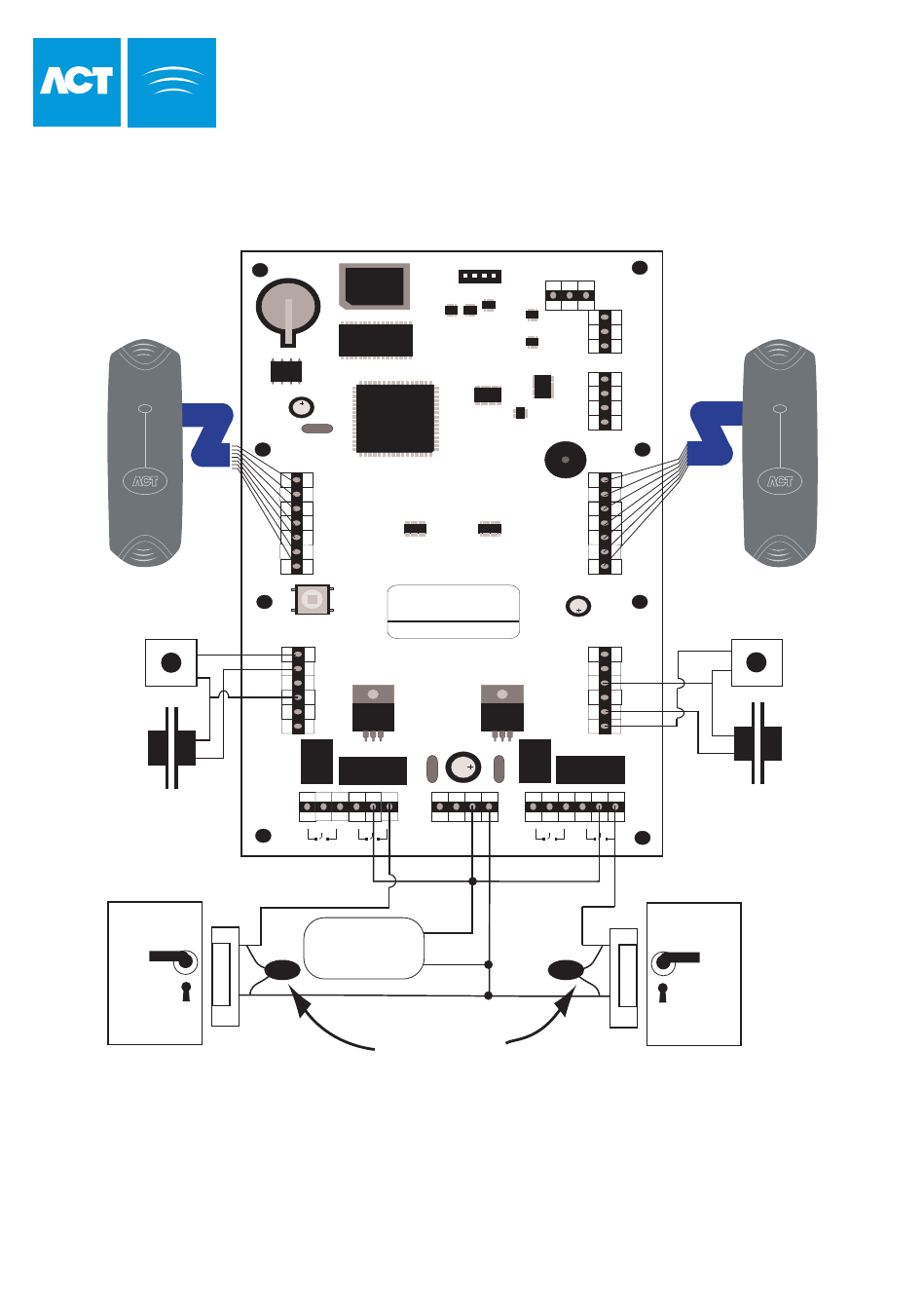
This illustration shows wiring
for normally de-energised
locks. If normally energised
locks are required, use the
N/C relay contacts.
Note:
If the Mains Present or Door
Contact inputs are not used,
they should be linked to 0V
Door 2
Release Button
Door 2 Contact
Release Button
Door 1
Door 1 Contact
Card/Proximity or Pin
Reader - Door 2
Card/Proximity or Pin
Reader - Door 1
Important!
Always Place Varistor
Across Lock Terminals
Door 2
Door 1
12V DC
Power Supply
12V
0V
-
D
C
Page 21 of 32
Typical ACT2000 Configuration
(Standalone)