Vertical position alignment – Grizzly Horizontal/Vertical Rotary Table G9298 User Manual
Page 12
-10-
g9298/g9299/g9300 rotary table
6. Move the mill table along the X-axis to the
position calculated in
Step 5.
7. repeat these steps with the mill table
y-axis.
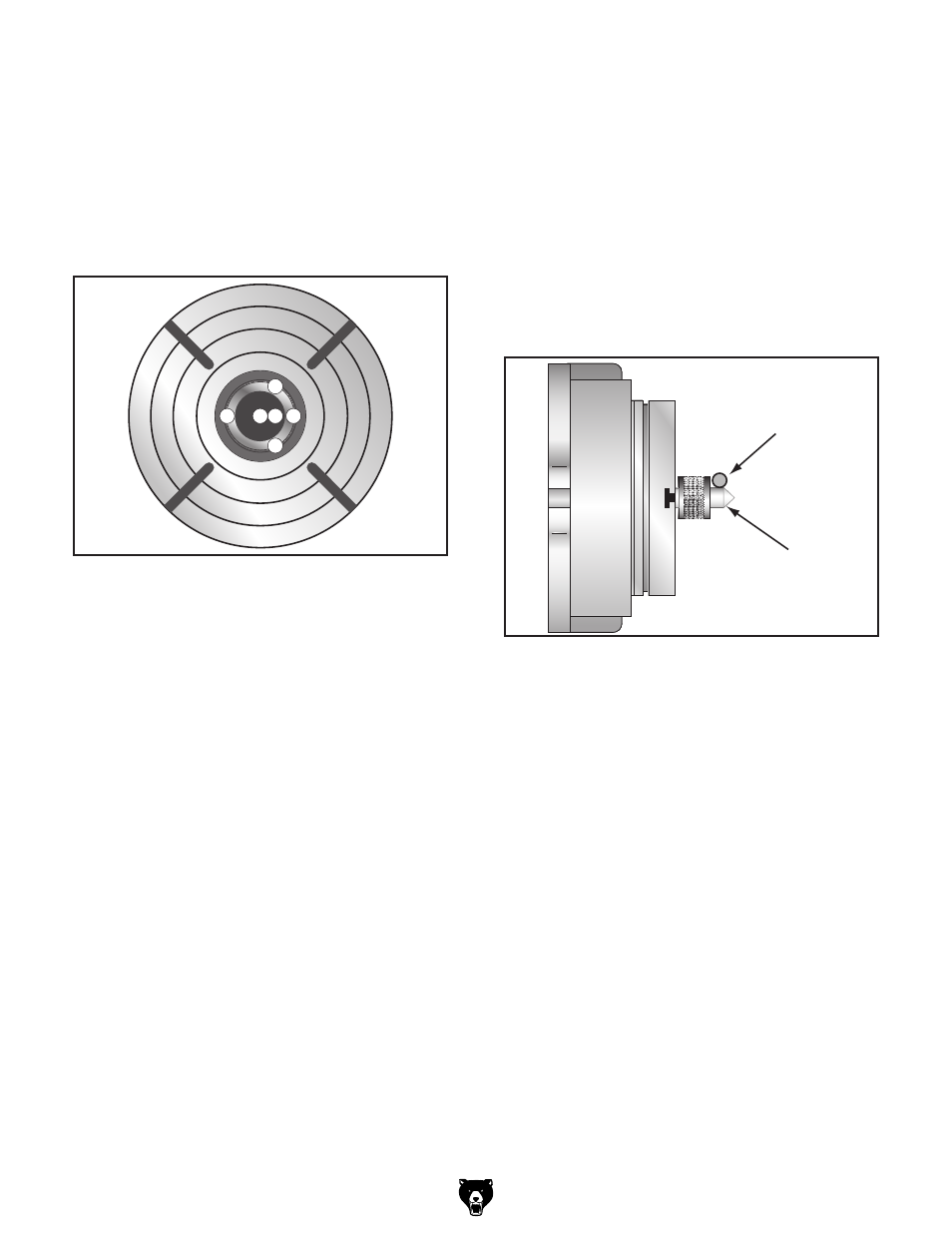
Note: Use the pattern illustrated in Figure 5
to aid in positioning the edge finder for the
above procedure.
1
2
3 4
5
6
figure 5. the six positions of the edge finder.
Vertical position Alignment
if the alignment keys are not used, it is a good
idea to verify the rotary table alignment front-to-
back with the mill spindle.
To verify the front-to-back alignment of the
rotary table:
1. disConneCt Mill FroM poWer!
2. Mount a test indicator on the mill spindle and
position the indicator tip on one end of the
rotary table face.
3. Move the mill table along the y-axis and note
any deviations in the test indicator.
— if a deviation is found, loosen the rotary
table mounting hex nuts, tap the rotary
table into the proper position, then re-tight-
en the mounting hex nuts.
4. repeat Step 3 until the entire rotary table
face is properly aligned with the mill spindle.
To center the rotary table with the mill spin-
dle:
1. Fully seat a lathe center into the rotary table
spindle.
Note: Any runout of the center will have to be
determined and accounted for in the following
steps.
2. use an edge finder mounted in the mill spin-
dle to find the center's edge (see the illustra-
tion in
figure 6).
Edge
Finder
Lathe
Center
Rotary
Table
Top View
figure 6. top view of the rotary table with an
edge finder and center.
3. Measure the diameter of the center where the
edge finder made proper contact, divide this
number in half, then add half of the diameter
of the edge finder. the result is the amount
you need to move the mill table along the
y-axis to center the rotary table with the mill
spindle.
Note: Be sure to take into account any back-
lash when moving the mill table.