Spindle alignment, Horizontal position alignment – Grizzly Horizontal/Vertical Rotary Table G9298 User Manual
Page 11
-9-
g9298/g9299/g9300 rotary table
Spindle Alignment
Whether the rotary table is mounted horizontally
or vertically, you must align the centers of the
rotary table and mill spindle to achieve quality
results.
there are many ways to align the rotary table,
and it is up to the machinist and his capabilities to
decide which approach is best.
Horizontal position Alignment
two methods are described below for aligning
the spindles when the rotary table is mounted
horizontally.
To use a test indicator to align the rotary
table:
1. disConneCt Mill FroM poWer!
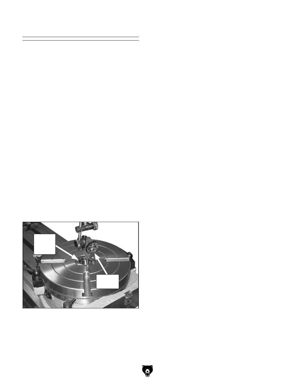
2. Mount a test indicator on the mill spindle and
position the indicator tip on the inside vertical
surface of the rotary table spindle bore, as
shown in
figure 4.
Note: Refer to Accessories on Page 15 for
test indicator options from Grizzly.
figure 4. test indicator properly positioned.
test
indicator
spindle
Bore
step
3. turn the mill spindle so that the test indicator
is aligned to the X-axis of the mill table.
Note: For best results, turn the mill spindle in
only one direction.
4. slowly move the mill table until the test indi-
cator reads zero deviation.
5. rotate the mill spindle and test indicator 90°,
then repeat
Step 4.
6. repeat Step 5 until the test indicator reads
zero deviation in all four directions.
Tip: Use a mirror to read the indicator when
it is facing away from you.
To use an edge finder to align the rotary
table:
1. Mount an edge finder into the mill spindle,
then position it roughly in the center of the
rotary table spindle bore and below the rotary
table surface.
2. turn the spindle ON and set the speed to
800–1000 rpM, then slowly move the mill
table along the X-axis in one direction.
3. When you find the edge of the rotary table
spindle bore, note the position of the table on
the handwheel dial.
Note: When recording the mill table position,
take into account the backlash that is usually
present in the leadscrew.
4. slowly move the mill table in the opposite
direction until you again find the edge of the
spindle bore, then note the table's position on
the handwheel dial.
5. Calculate the difference of the mill table posi-
tions noted in
Steps 3–4, then subtract
1
⁄
2
the
diameter of the edge finder.