Lower blade guide assembly adjustment – Grizzly G0659 User Manual
Page 30
-28-
g0659
9" x 14" Vertical Metal-Cutting Bandsaw
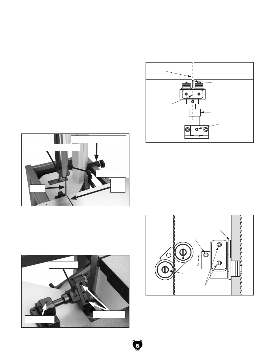
5. Wearing gloves, hold the blade in-line with
the path of the saw and centered over the slot
in the table. rotate the eccentric shaft so the
blade guide assembly is centered over the
blade, as shown in
figure 39, then tighten
set screw A.
IVWaZ
7aVYZ
>c"a^cZL^i]EVi]
D[HVl
:XXZcig^XH]V[i
HZiHXgZl6
8ZciZgZY
7aVYZ
Hadi
figure 39. lower blade guide.
6. rotate the blade guide assembly and apply
just enough pressure to hold the blade flat
against both guide rollers. rotate the eccen-
tric spindles so their slots are oriented verti-
cally, as shown in
figure 40. this positions
the blade guides in the center of their range
of motion to facilitate later adjustments.
7. tighten set screws C.
HZiHXgZl7
HZiHXgZlh8
7aVYZ ;aVc\Z :XXZcig^X figure 40. Blade guide positioning. Lower Blade Guide Assembly 3. open the upper wheel door, loosen the blade guard cap screw and remove the blade guard. 4. loosen set screws A, B, and C on the lower blade guide assembly ( figure 38). When it is not possible to accomplish the neces- To position the lower blade guide assembly: 1. disConneCt BAndsAW FroM poWer! 2. Move the saw frame forward until it is up to, but not yet entering the slot in the table, as figure 37, then lock the frame in place using the saw frame stop clamp. figure 37. Blade guide setup. saw Frame stop Clamp Blade table slot Blade guard Blade guard Cap screw figure 38. lower blade guide assembly. set screw A set screw B set screws C set screws C
He^cYaZh
Adjustment
sary blade guide positioning with the eccentric
spindles alone, the entire blade guide assembly
must be re-adjusted. First position the lower
blade guide assembly, then the upper blade guide
assembly.
shown in