FUJITSU M3096EX/GX User Manual
Page 51
C – 2
(4)
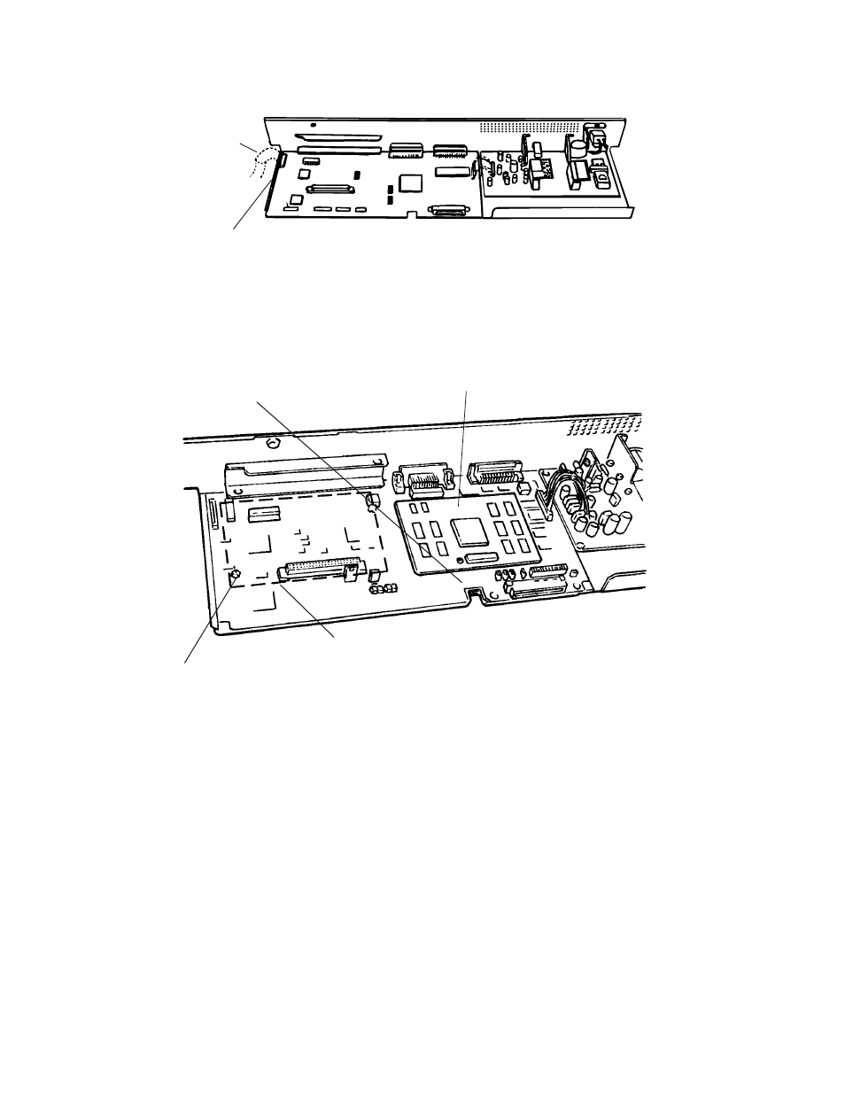
Remove the flat cable connector and detach the power supply and PCA assembly.
Flat cable connector
Flat cable
(5)
Connect the IPC-2 option board connector and tighten the screw.
(6)
Where a CMP-2 is installed, remove the screw from the memory board and detach the
memory board. Connect the CMP-2 option board connector and tighten the screw.
(7)
Attach the power supply and PCA assembly in the reverse order of removal.
Screw for IPC-2
IPC-2 option board
Screw for memory or CMP-2 (M3096GX)
CMP-2 option board or memory PCA (M3096GX)
(not shown)
See also other documents in the category FUJITSU Scanners:
- fi-5015C (26 pages)
- M3093GX\DG (7 pages)
- M3099EX (100 pages)
- S500M (24 pages)
- M3096GX (53 pages)
- M3093GX (50 pages)
- fi-4750L (95 pages)
- Image Scanner fi-5650C (161 pages)
- C150-E194-01EN (38 pages)
- fi-4120C2 (130 pages)
- fi-4010CU (2 pages)
- SCANSNAP P2WW-2301-01ENZ0 (90 pages)
- fi-5110C (137 pages)
- fi-4530C (132 pages)
- fi-4110CU (40 pages)
- FI-6140 (20 pages)
- fi-5120C (28 pages)
- M3091DC (51 pages)
- fi-5110EOX (135 pages)
- SCANPARTNER 620C (26 pages)
- fi-4750C (94 pages)
- fi-5220C (28 pages)
- fi-5530C (28 pages)
- SCANSNAP P2WW-2300-01ENZ0 (81 pages)
- SCANSNAP NETWORK SCANNER N1800 (23 pages)
- Network Scanner fi-6010N (21 pages)
- fi-4640S (61 pages)
- SCANSNAP S300M (38 pages)
- M3093DE (51 pages)
- fi-5750C (40 pages)
- Image Scanner fi-6230 (222 pages)
- fi-6230 (211 pages)
- C150-E187-01EN (94 pages)
- Mobile Color Scanner (65 pages)
- SCANPARTNER 600C (95 pages)
- IMAGE FI-5530C2 (179 pages)
- C150-E140-03EN (63 pages)
- fi-4220C2 (141 pages)
- CardMinder P2WW-2640-01ENZ0 (40 pages)
- M3097DG (70 pages)
- SCANSNAP! FI-4110EOX2 (97 pages)
- fi-60F (55 pages)
- ScanSnap Upgrade P2WW-1860-01EN Scanner (55 pages)
- fi-4340C (114 pages)
- fi-4120C (180 pages)