2 external monitor – Furuno FR-8122 User Manual
Page 37
4. OPTIONAL EQUIPMENT
4-3
4.2 External Monitor
You can display the radar image on an external monitor which accepts industrial standard
VGA input using the optional RGB kit OP03-195. Supply monitor and interconnection cable
(with HD-15P connectors of male, three rows of 15 pins) locally.
Necessary parts for external monitor
Name: RGB
kit
Type: OP03-195
Code No.: 008-553-110
Name Type Code
No.
Qty
RGB board
03P9492
008-553-680
1
Flat cable
SML2SC34-4X50BDP.5S4
000-155-457
1
Cable assy
15SDS/XHP10-005
000-144-511
1
EMI core
RFC-6
000-144-132-10
1
1. Unscrew all connector nuts at the rear of the display unit.
2. Unfasten all screws to remove the display cover.
3. Disconnect the printed circuit board 03P9415 and 03P9413.
Before disconnecting the 03P9413, disconnect J601 and J604 at the back of the board.
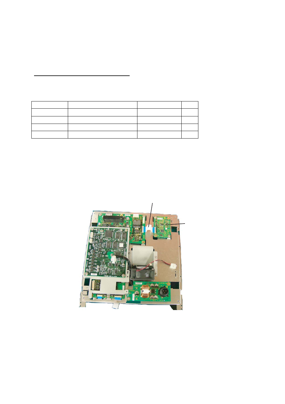
4. Mount the RGB board with two screws and connect the flat cable at the location shown
in the figure below.
Flat cable
RGB board
5. Remount 03P9415 and 03P9413 at their original locations and display cover.