2 wiring the power supply unit, Cabling – Furuno FR-8122 User Manual
Page 26
2. WIRING
2-2
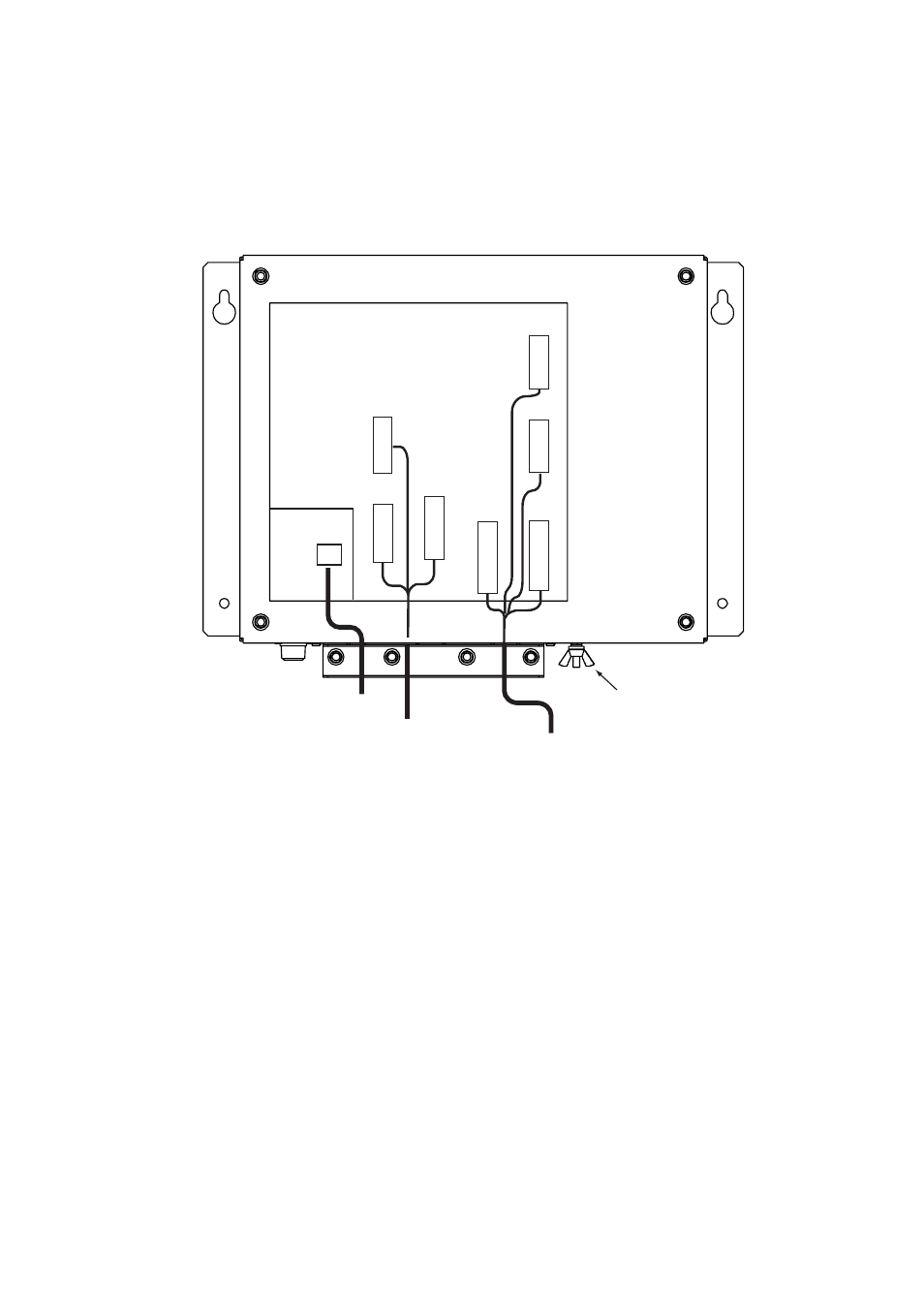
2.2 Wiring the Power Supply Unit
Cabling
1. Unfasten four screws to remove the cable clamp.
2. Unfasten four screws to remove the cover.
3. Attach the connectors of three cables as shown in the figure below.
POWER Board 03P9419
J1 3P
VL3P-VV-S2X
2C-AA050
cable
(to 12-24 VDC)
MJ-B24
LPF0011-050
cable
(to display unit)
V
H
9
N
H
13
V
H
4
J3
J4
J5
Ground
terminal
V
H
1
0
J12
N
H
1
4
J14
V
H
5
J13
V
H
2
J11
Antenna cable
RW-9771
(03S9771)
4. Lay three cables in respective slots referring to the figure above.
5. Reattach the cover and the cable clamp.
6. Connect a ground wire (local supply, IV-2sq) between the ground terminal and ship’s
ground.
See also other documents in the category Furuno Sports and recreation:
- FAR-2805 Series (169 pages)
- FR-8062 (2 pages)
- CH-37 (90 pages)
- CH-37 (71 pages)
- FAR-2XX7 (4 pages)
- FAR-2XX7 (2 pages)
- FELCOM16 (4 pages)
- FRS-1000B (8 pages)
- FRS1000 (8 pages)
- Ls4100 (48 pages)
- 520 (73 pages)
- Marine Radar (24 pages)
- 1944C-BB (233 pages)
- 1733C (260 pages)
- FR-2105 (197 pages)
- FMD-8010 (50 pages)
- GD-1900C (260 pages)
- Black Box Video Sounder FCV-1200BB (2 pages)
- FR-1505 MARK-3 (4 pages)
- 1762 (252 pages)
- NAVnet DRS12A (44 pages)
- FAR-2137S (8 pages)
- FAR-2127 (136 pages)
- FA30 (6 pages)
- Satellite Compass SC-50/110 (30 pages)
- 1715 (2 pages)
- 1715 (48 pages)
- 1734C (55 pages)
- GD-1720C (53 pages)
- Mu 120c (2 pages)
- NAVNET GD-1920C (239 pages)
- CI-80 (41 pages)
- FAR-28x7 Series (299 pages)
- FAR-2837S (8 pages)
- BBWX1 (2 pages)
- 851 MARK-2 (47 pages)
- 851 MARK-2 (37 pages)
- BBFF3 (1 page)
- CSH-53 (106 pages)
- CSH-53 (108 pages)
- FCV295 (53 pages)
- FR1500 Mk3 (79 pages)
- FI-50 Series (2 pages)
- FCV-1150 (32 pages)