Adjustment, 1 checking magnetron heater voltage, Danger – Furuno 851 MARK-2 User Manual
Page 24
3-1
3. ADJUSTMENT
3.1 Checking magnetron heater voltage
Magnetron heater voltage is formed on the MD Board (03P9235) of the antenna
unit, and is preadjusted at the factory for use with any length of signal cable.
Therefore no adjustment is required. However, check magnetron heater voltage
as follows:
1. Turn on the radar and leave it in stand-by.
2. Open the antenna cover.
3. Unfasten four screws to remove the RF section cover.
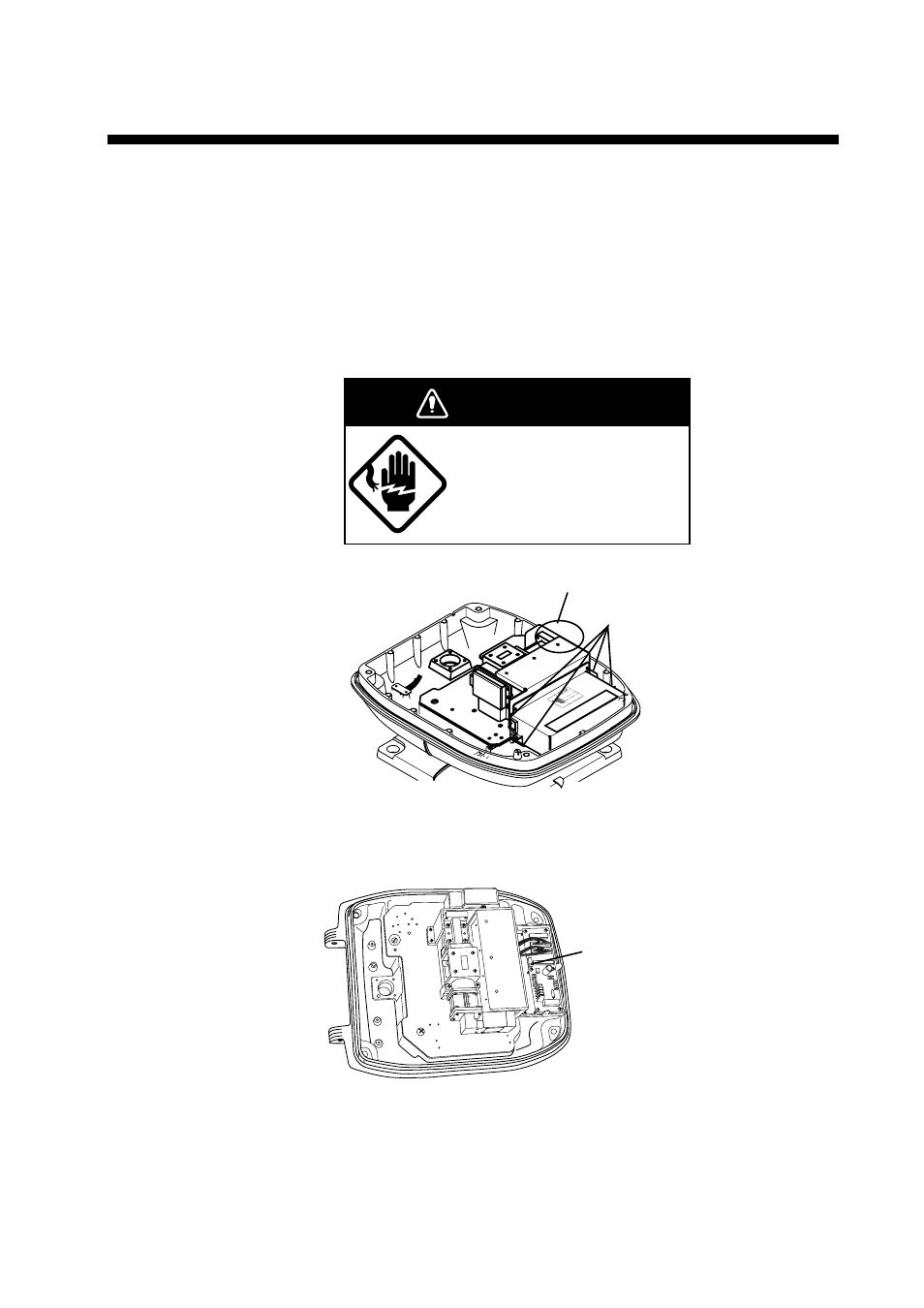
ELECTRICAL SHOCK HAZARD
This check is done with the
power on
DO NOT touch
the magnetron.
DANGER
Four screws
Magnetron
Figure 3-1 Antenna unit, cover opened
4. Connect a multimeter, set to 10 VDC range, between test point J825#4 and
J825#6 (GND) on the RTB Board (03P9249).
Measure voltage
at this connector
(J825).
Figure 3-2 Antenna unit, cover opened
5. Confirm the meter reads 7.6 V
±
0.1 V.
6. Close the antenna cover and tighten the cover fixing screws.
- FAR-2805 Series (169 pages)
- FR-8062 (2 pages)
- FR-8122 (56 pages)
- CH-37 (90 pages)
- CH-37 (71 pages)
- FAR-2XX7 (2 pages)
- FAR-2XX7 (4 pages)
- FELCOM16 (4 pages)
- FRS-1000B (8 pages)
- FRS1000 (8 pages)
- Ls4100 (48 pages)
- 520 (73 pages)
- Marine Radar (24 pages)
- 1944C-BB (233 pages)
- 1733C (260 pages)
- FR-2105 (197 pages)
- FMD-8010 (50 pages)
- GD-1900C (260 pages)
- Black Box Video Sounder FCV-1200BB (2 pages)
- FR-1505 MARK-3 (4 pages)
- 1762 (252 pages)
- NAVnet DRS12A (44 pages)
- FAR-2127 (136 pages)
- FAR-2137S (8 pages)
- FA30 (6 pages)
- Satellite Compass SC-50/110 (30 pages)
- 1715 (48 pages)
- 1715 (2 pages)
- 1734C (55 pages)
- GD-1720C (53 pages)
- Mu 120c (2 pages)
- NAVNET GD-1920C (239 pages)
- CI-80 (41 pages)
- FAR-28x7 Series (299 pages)
- FAR-2837S (8 pages)
- BBWX1 (2 pages)
- 851 MARK-2 (47 pages)
- BBFF3 (1 page)
- CSH-53 (106 pages)
- CSH-53 (108 pages)
- FCV295 (53 pages)
- FR1500 Mk3 (79 pages)
- FI-50 Series (2 pages)
- FCV-1150 (32 pages)