7 mounting the display unit – Furuno 851 MARK-2 User Manual
Page 17
1. MOUNTING
1-11
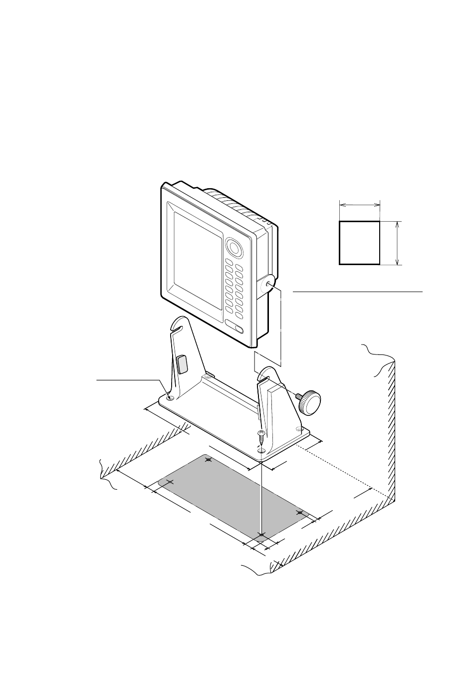
1.7 Mounting the Display Unit
The display unit is designed to be mounted on a tabletop.
1. Using the hanger as a template, mark screw locations in the mounting
location.
2. Fix the hanger to the mounting location with four 5 x 20 tapping screws
(supplied).
3. Fit the knob bolts to the display unit.
4. Install the display unit in the hanger.
5. Tighten the knob bolts securely.
*140
(5.51")
10
(0.39")
238
(9.37")
15
(0.59")
15
(0.59") *80
(3.15")
*80
(3.15")
100
(3.94")
20
(0.79")
268
(10.55")
130
(5.12")
4 -
∅
6
FIXING HOLES
* : SERVICING CLEARANCE
222(8.7")
236(9.3")
Cutout dimensions for flushmount
**
**
**: If the mounting location is
subject to heavy vibration,
fasten the display unit in the
hanger perpendicularly so that
it contacts the rubber cushions.
Figure 1-17 How to mount the display unit
- FAR-2805 Series (169 pages)
- FR-8062 (2 pages)
- FR-8122 (56 pages)
- CH-37 (90 pages)
- CH-37 (71 pages)
- FAR-2XX7 (4 pages)
- FAR-2XX7 (2 pages)
- FELCOM16 (4 pages)
- FRS-1000B (8 pages)
- FRS1000 (8 pages)
- Ls4100 (48 pages)
- 520 (73 pages)
- Marine Radar (24 pages)
- 1944C-BB (233 pages)
- 1733C (260 pages)
- FR-2105 (197 pages)
- FMD-8010 (50 pages)
- GD-1900C (260 pages)
- Black Box Video Sounder FCV-1200BB (2 pages)
- FR-1505 MARK-3 (4 pages)
- 1762 (252 pages)
- NAVnet DRS12A (44 pages)
- FAR-2137S (8 pages)
- FAR-2127 (136 pages)
- FA30 (6 pages)
- Satellite Compass SC-50/110 (30 pages)
- 1715 (2 pages)
- 1715 (48 pages)
- 1734C (55 pages)
- GD-1720C (53 pages)
- Mu 120c (2 pages)
- NAVNET GD-1920C (239 pages)
- CI-80 (41 pages)
- FAR-28x7 Series (299 pages)
- FAR-2837S (8 pages)
- BBWX1 (2 pages)
- 851 MARK-2 (47 pages)
- BBFF3 (1 page)
- CSH-53 (106 pages)
- CSH-53 (108 pages)
- FCV295 (53 pages)
- FR1500 Mk3 (79 pages)
- FI-50 Series (2 pages)
- FCV-1150 (32 pages)