Signal cable connection – Furuno 851 MARK-2 User Manual
Page 19
2. WIRING
2-2
FM-C10FPD002-200
000-143-891
20m
FM-C10FPD002-300
000-143-890
30m
*2:The following cables are optionally supplied for heading sensor connection.
Type
Code no.
Remarks
FM-C6FPD001-050
000-143-897
PG-1000 (5m)
FM-C6FPD001-100
000-143-898
PG-1000 (10m)
*3:The following cables can be used for NMEA 0183 format connection.
Type
Code no.
Remarks
FM-C6FPD002-050
000-143-895
6P-6P(5m), Cross type
FM-C6FPD002-100
000-143-896
6P-6P(10m) , Cross type
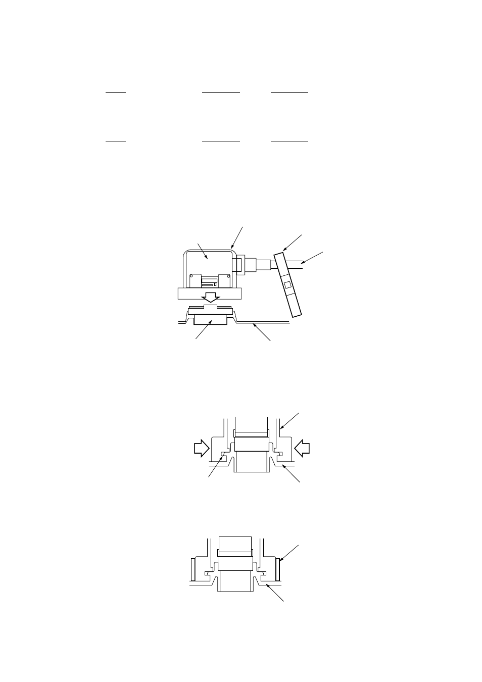
Signal cable connection
1. Connect the signal cable to DJ-1 on the rear panel of the display unit.
Rubber cover
DJ Connector
Boot-band
Cable
Display unit
DJ-1
Figure 2-2
2. Cover the connector with the rubber cover. The projection on the connector
base is inserted into the groove on the rubber cover.
Display unit
Rubber cover
Grasp
Grasp
Groove
Figure 2-3
3. Put the boot-band as shown below, and tighten it.
Display Unit
Boot-band
Figure 2-4
- FAR-2805 Series (169 pages)
- FR-8062 (2 pages)
- FR-8122 (56 pages)
- CH-37 (90 pages)
- CH-37 (71 pages)
- FAR-2XX7 (4 pages)
- FAR-2XX7 (2 pages)
- FELCOM16 (4 pages)
- FRS-1000B (8 pages)
- FRS1000 (8 pages)
- Ls4100 (48 pages)
- 520 (73 pages)
- Marine Radar (24 pages)
- 1944C-BB (233 pages)
- 1733C (260 pages)
- FR-2105 (197 pages)
- FMD-8010 (50 pages)
- GD-1900C (260 pages)
- Black Box Video Sounder FCV-1200BB (2 pages)
- FR-1505 MARK-3 (4 pages)
- 1762 (252 pages)
- NAVnet DRS12A (44 pages)
- FAR-2137S (8 pages)
- FAR-2127 (136 pages)
- FA30 (6 pages)
- Satellite Compass SC-50/110 (30 pages)
- 1715 (2 pages)
- 1715 (48 pages)
- 1734C (55 pages)
- GD-1720C (53 pages)
- Mu 120c (2 pages)
- NAVNET GD-1920C (239 pages)
- CI-80 (41 pages)
- FAR-28x7 Series (299 pages)
- FAR-2837S (8 pages)
- BBWX1 (2 pages)
- 851 MARK-2 (47 pages)
- BBFF3 (1 page)
- CSH-53 (106 pages)
- CSH-53 (108 pages)
- FCV295 (53 pages)
- FR1500 Mk3 (79 pages)
- FI-50 Series (2 pages)
- FCV-1150 (32 pages)