4 power-on sequence, Cl-sh8669, I/f ata – FUJITSU MPF3XXXAT User Manual
Page 50
C141-E099-01EN
4 - 5
HDC
SH7660
RDC
CL-SH3512
MCU
ARM7TDMI
CL-SH8669
Himalaya 1.5
– PIO Mode-4
– Multiword DMA Mode-2
– Ultra DMA Mode-4
SVC
HA13626
SPM/VCM
control
PB-15
21.5 to 37.8 MB/s
R/W
Bandwidth = 110.0 MB/s
Buffer
Head IC
TLS26B454
Data Buffer
256K
×
16 bits
Option
(1024K
×
16 bits)
Flash ROM
64K
×
16 bits
Series Termination
40.0 MHz
Console I/F (RS232C)
Switch
I/F
ATA
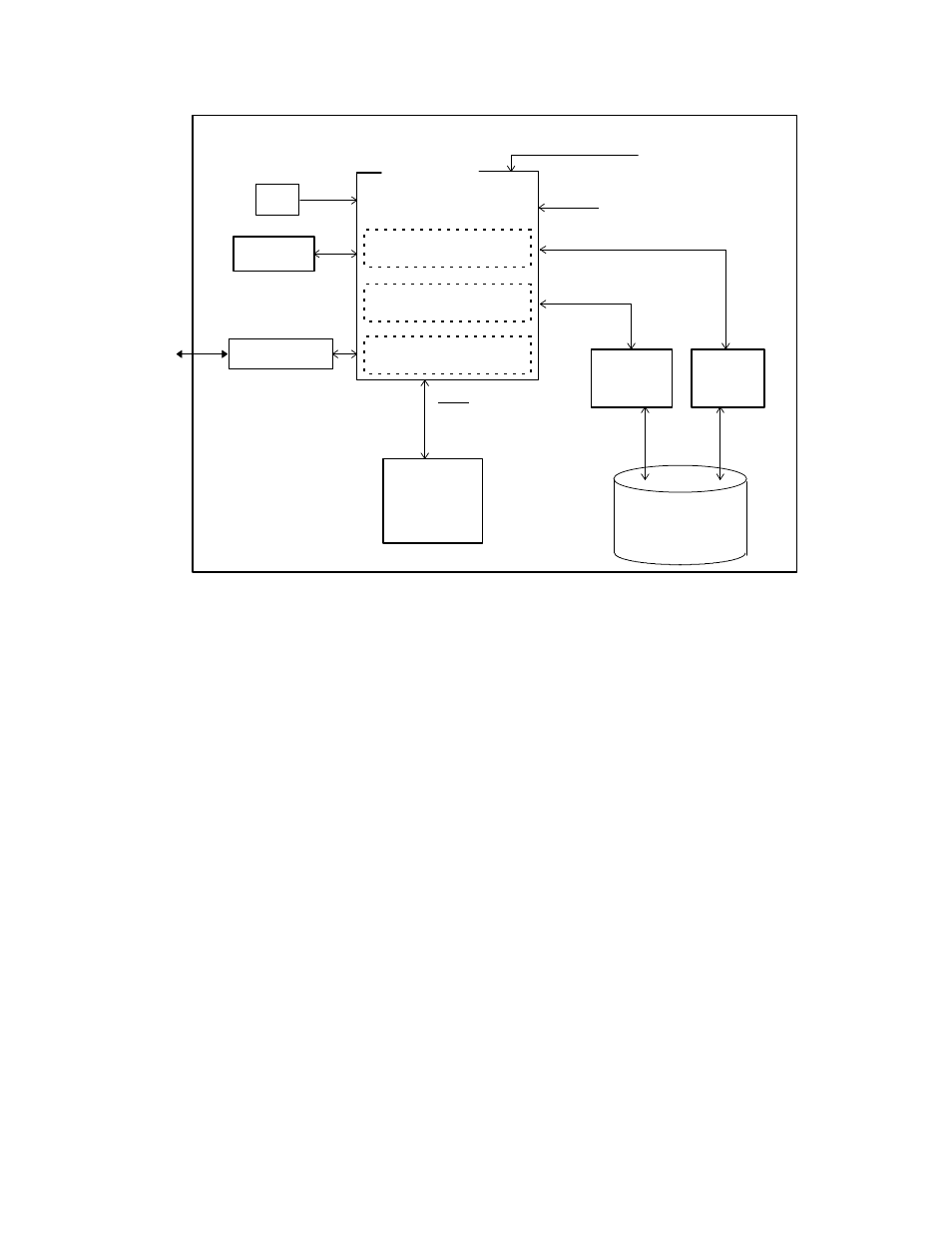
Figure 4.2
MPF3xxxAT Block diagram
4.4
Power-on Sequence
Figure 4.3 describes the operation sequence of the disk drive at power-on. The outline is
described below.
a) After the power is turned on, the disk drive executes the MPU bus test, internal register
read/write test, and work RAM read/write test. When the self-diagnosis terminates
successfully, the disk drive starts the spindle motor.
b) The disk drive executes self-diagnosis (data buffer read/write test) after enabling response
to the ATA bus.
c) After confirming that the spindle motor has reached rated speed, the disk drive releases the
heads from the actuator magnet lock mechanism by applying current to the VCM. This
unlocks the heads which are parked at the inner circumference of the disks.
d) The disk drive positions the heads onto the SA area and reads out the system information.
e) The disk drive executes self-seek-calibration. This collects data for VCM torque and
mechanical external forces applied to the actuator, and updates the calibrating value.
f) The drive becomes ready. The host can issue commands.