Input/output signal, 1 inputs from sensors, Tb1 in the junction box – Furuno FA-100 User Manual
Page 21
15
3. INPUT/OUTPUT SIGNAL
3.1 Inputs from Sensors
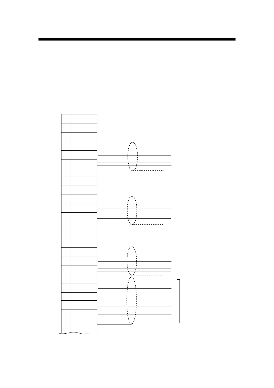
There are three input ports (SENSOR 1, 2 and 3) which are based on the IEC
61162-1/2. The protocol is RS422. If there is no HDT signal from a gyrocompass,
connect the gyrocompass signal (Synchro or step signal) to the “AD-10 IN” port
(D-sub 9 pins) of the transponder unit via the FURUNO A/D Converter AD-100 (See
page 16).
1 TD3-A
2 TD3-B
3 GND ISO
4 RD3-A
5 RD3-B
6 GND ISO
7 TD2-A
8 TD2-B
9 GND ISO
10 RD2-A
11 RD2-B
12 GND ISO
13 TD1-A
14 TD1-B
15 GND ISO
16 RD1-A
17 RD1-B
18 GND ISO
19 TD5-A
20 TD5-B
21 GND
22 RD5-A
23 RD5-B
24 GND
TB1 in the junction box
GPS navigator only
TTYCS-1Q
Isolated GND
Heading Signal (HDT)
TTYCS-1Q
Isolated GND
Speed Signal (SOG)
TTYCS-1Q
Isolated GND
TTYCS-1Q
GND 0V
DGPS
Beacon
Receiver
SENSOR 3 (EXT GPS IN)
SENSOR 2
SENSOR 1
(4 cores twisted)
- 2817-D (136 pages)
- 841 MARK-2 (58 pages)
- FAR-2157-BB (111 pages)
- UAIS TRANSPONDER FA-150 (4 pages)
- NAVNET 1763C (260 pages)
- FR-1710 (78 pages)
- FAR-2807 (52 pages)
- MARINERADAR FR-8062 (56 pages)
- 1935 (48 pages)
- FR-7062 (52 pages)
- FR-7252 (48 pages)
- COLOR VIDEO PLOTTER 1943C (251 pages)
- NAVPILOT 520 (73 pages)
- FAR-2167DS (111 pages)
- NAVpilot NAVpilot-500 (73 pages)
- FAR-2827 (135 pages)
- NAVNET 1823C (260 pages)
- FR-2155 (89 pages)
- NAVNET 1943 (248 pages)
- 1622 (24 pages)
- FR-2115/2125 (79 pages)
- 1942 MARK-2 (52 pages)
- 1942 MARK-2 (46 pages)
- 2137S (123 pages)
- 1832 (62 pages)
- 1832 (64 pages)
- 1832 (63 pages)
- FAR-2167DS-D (111 pages)
- 821 (64 pages)
- FR-8251 (69 pages)
- FR-2135S (82 pages)
- FAR-2127-BB (136 pages)
- NX-700A/B (89 pages)
- MSC.36(63) (1 page)
- IF-1500AIS (12 pages)
- FR-8051 (64 pages)
- FAR-2157 (111 pages)
- FAR-2157 (8 pages)
- 1712 (27 pages)
- UAIS TRANPONDER FA-150 (128 pages)
- FAR-2107(-BB) (312 pages)
- NATVET 1824C (239 pages)
- FAR-2107 (280 pages)
- NAVPILOT 500 (73 pages)