Appendix a. useful features, Appendix a.1. module positions, Appendix a.1.1 – FieldServer Optomux FS-8700-17 User Manual
Page 12: Static specification, O appendix a.1.1
FS-8700-17_Opto22.doc Manual
Page 10 of 24
FieldServer Technologies 1991 Tarob Court Milpitas, California 95035 USA Web: www.fieldserver.com
Tel: (408) 262 2299 Fax: (408) 262 2269 Toll Free: (888) 509 1970 email: [email protected]
Appendix A. Useful Features
Appendix A.1. Module Positions
Appendix A.1.1.
Static Specifi cation
Specify module positions statically by
Using Address and Length
Using the Opto22_Mask parameter
If more than one method is used for module position specification, the driver evaluates the specification in the order listed above. Thus if address & length are
specified as well as the opto22_mask, the driver will use the address and length.
Take care to ensure that the Data Array used for storage has a data format suitable for storing the data type returned by the command. Also take care to ensure
that you understand the scaling of the data returned by the Optomux device. There are parameters that you can add to a Map Descriptor to have the driver scale
the value. This is discussed in the FieldServer Configuration Manual.
A.1.1.1 .
Map Descript or Exam ple - Static Specificati on using Address a nd Length.
This example shows a Map Descriptor which reads analog inputs from an Optomux Device. The address and length tell the driver which inputs to read. This style
of configuration is not suited to writing/commanding since the driver builds its payload based entirely on the address and length. It does not look in the Data Array
to see which positions must be written with a ‘1’ or a ‘0’
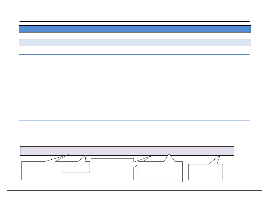
Map_Descriptor_Name , Data_Array_Name
, Data_Array_Offset , Function
, Node_Name , Address , Length
, Scan_Interval , Opto22_function
DEVICE77_STAT
, ANA_DATA
, 0
, Rdbc
, DEV77
, 2
, 15
, 1.0s
, READ ANALOG INPUTS
Data read from the
Optomux Device is
placed in this array.
Starting at this
array position.
The first module position
that is read is position 2.
Module positions are
numbered 1 to 16.
Data from 15 module
positions must be read.
Thus starting at 2, the last
module position read is 16.
This is the Optomux
Driver function that
must be performed.