FUJITSU MAW3073NC/NP User Manual
Page 56
4-6
C141-E226
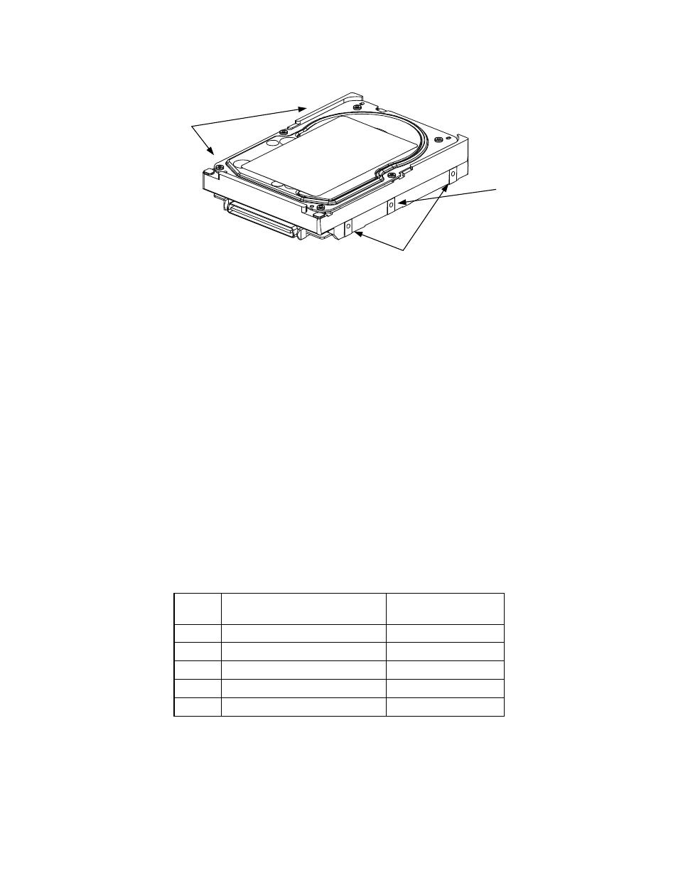
Holes for
mounting screw
1
2
3
4
In case of using a
center hole, use it in
combination with the
holes of both ends.
Holes for mounting screw
Use four holes (No.1 to No.4) to mount.
Figure 4.5
Limitation of side-mounting
(4)
Limitation of bottom-mounting
Use all four mounting holes on the bottom face.
(5) Environmental
temperature
Temperature condition at installed in a cabinet is indicated with ambient temperature measured
30 mm from the disk drive. At designing the system cabinet, consider following points.
• Make a suitable air flow so that the DE surface temperature never exceed 60°C.
• Cool the PCA side especially with air circulation inside the cabinet. Confirm the cooling effect
by measuring the surface temperature of specific ICs and the DE. These measurement results
must satisfy the temperature condition listed in Table 4.1.
Table 4.1
Surface temperature check point
No.
Measurement point
Max. temperature on
package
1 DE
surface
60°C
2
Read channel LSI
80°C
3 VCM/SPM
Driver
93°C
4 HDC
91°C
5 MPU
90°C