FUJITSU MPG3XXXAH User Manual
Page 42
C141-E112-01EN
3 - 11
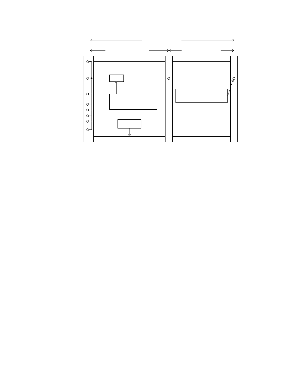
open
Connector 2
Connector 1
System Board
Connector
Pin 2 (Ground)
Pin 19 (Ground)
Pin 22 (Ground)
Pin 24 (Ground)
Pin 26 (Ground)
Position 1
Pin 34 contact
(PDIAG-:CBLID- signal)
254.0 to 457.2 mm
(10 to 18 inch)
101.6 to 152.4 mm
(4 to 6 inch)
127.0 to 304.8 mm
(5 to 12 inch)
Symbolizes Pin 34
Conductor being cut
Pin 30 (Ground)
Pin 34
Pin 40 (Ground)
Figure 3.11 Cable configuration
b) Host system that do support Ultra DMA modes greater than mode 2 shall either connect
directly to the device without using a cable assembly, or determine the cable assembly type.
Determining the cable assembly type may be done either by the host sensing the condition of
the PDIAG-:CBLID- signal (see Figure 3.12), or by relying on information from the device
(see Figure 3.13). Hosts that rely on information from the device shall have a 0.047
µ
F
capacitor connected from the PDIAG-:CBLID- signal to ground. The tolerance on this
capacitor shall be 20% or less.
- XG Series P3NK-4452-01ENZD (614 pages)
- FPCAC14C (1 page)
- MCJ3230SS (161 pages)
- MBA3073NC (138 pages)
- T5140 (102 pages)
- T5140 (76 pages)
- MAM3367MC/MP (152 pages)
- MPC3045AH (185 pages)
- MB2142-02 (23 pages)
- MB15F86UL (6 pages)
- MHS2030AT (40 pages)
- MHW2100BS (296 pages)
- MHK2060AT (227 pages)
- Disk Drives MHK2060AT (227 pages)
- MCM3064SS (170 pages)
- Mainboard D1561 (45 pages)
- MHC2040AT (219 pages)
- D1961 (45 pages)
- DISK DRIVES MHM2100AT (231 pages)
- MHR2010AT (250 pages)
- MHZ2120BJ (320 pages)
- MCE3064AP (175 pages)
- LQFP-64P (16 pages)
- Solaris PCI GigabitEthernet 3.0 (115 pages)
- MAY2036RC (94 pages)
- MAB3091 (142 pages)
- MPE3XXXAT (191 pages)
- MHV2040AH (40 pages)
- MHW2040AC (278 pages)
- ETERNUSmgr P2X0-0202-01EN (64 pages)
- VSS Hardware Provider 2.1 (134 pages)
- MAG3182FC (61 pages)
- MAU3147NC/NP (130 pages)
- MAX3147RC (94 pages)
- MHV2160BT (296 pages)
- MHV2040AT (280 pages)
- MAW3300NC/NP (130 pages)
- DeskPower E623 (50 pages)
- MAG3182LC (133 pages)
- OPTICAL DISK DRIVES MDG3064UB (42 pages)
- MHF2021AT (225 pages)
- MHR2040AT (40 pages)
- Single Drive FTM7926FB (1 page)
- PG-FCS103 (98 pages)
- MAS3735FC (114 pages)