Printer interface, Modification of antenna circuit, Refer to page s-1 – Furuno FM-8700 User Manual
Page 20: Figure 10 cable entrance of printer interface
17
Printer Interface
Refer to page S-1.
10
9
8
7
6
5
4
3
2
1
TB1
RxD-C
RxD-H
TxD-C
TxD-H
RxD-C
RxD-H
TxD-C
TxD-H
-
+
Connect the connector coming
from pinter to "PRINTER"
port.
No. 1 FM-8700
No. 2 FM-8700
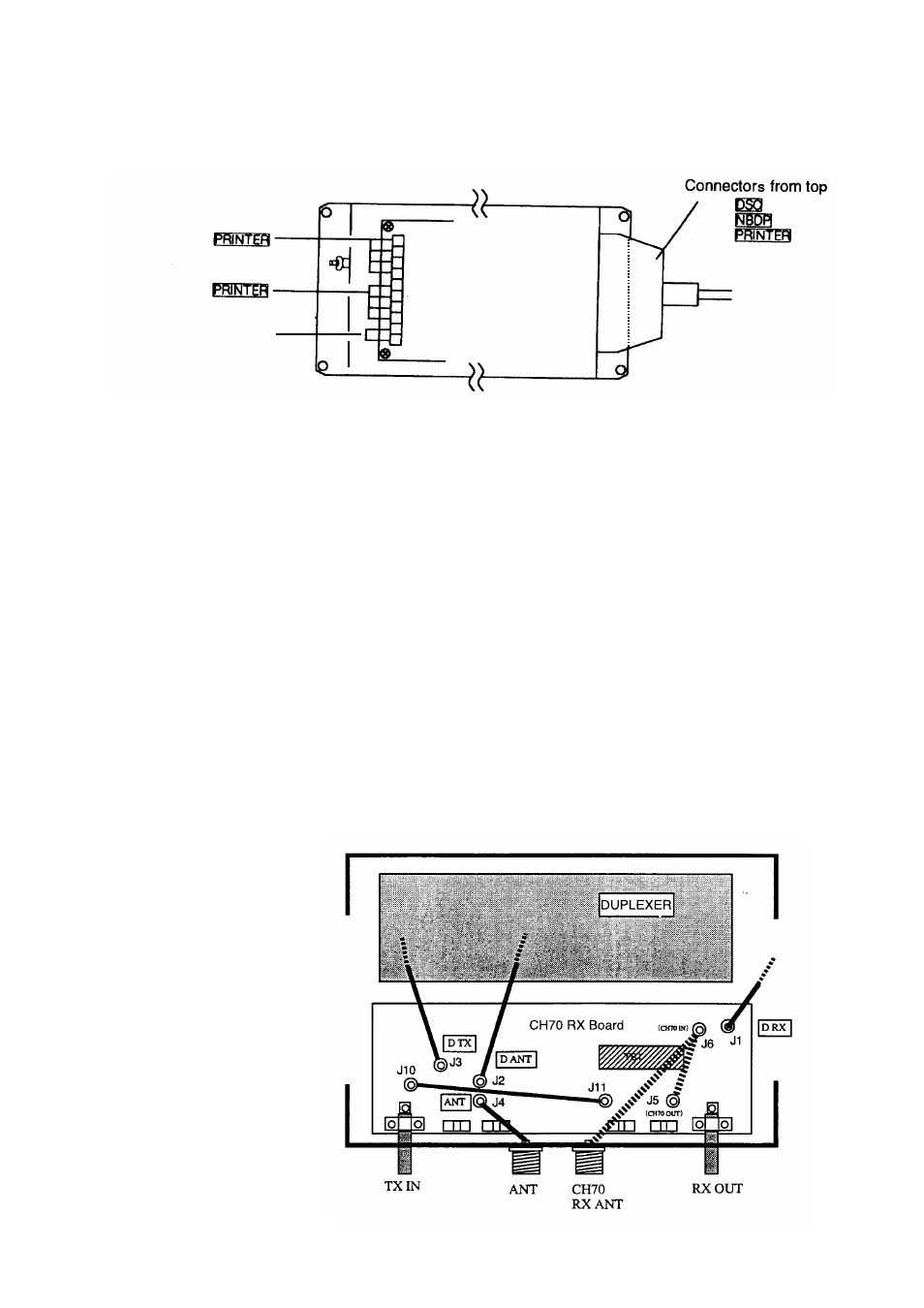
Figure 10 Cable entrance of Printer Interface
Modification of antenna circuit
The factory setting is individual use of antenna for TX and RX (two
antennas are needed).
If you want to ues a common antenna for TX and RX, do the
following modification.
1. Remove the cover of the Duplexer Unit.
2. Remove connector plug of J6, comming from CH70 RX ANT con-
nector. Wrap it with vinyl tape to insulate.
3. Attach connector assembly L-110 (supplied) between J5 and J6 .
24 VDC