Fisher & Paykel DS602I User Manual
Page 8
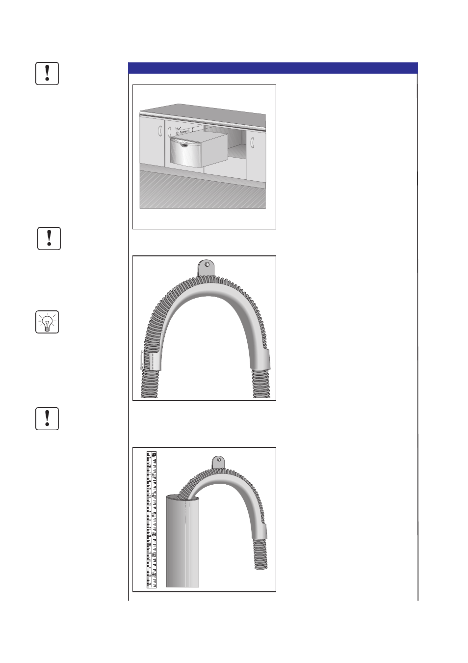
STEP 2.2 CONNECTING THE SERVICES
Ensure the edges of the
Service Hole are smooth
or covered. (See Step 1.2 -
Product Specifications &
Cavity Dimensions.) If the
Services Hole is through a
metal partition, the hole
must be protected with the
Edge Protector provided.
DO NOT adjust the length
of the Inlet Hose.
Turn the water valve ON
to check for any leaks,
before pushing the
DishDrawer back into its
cavity.
Attach the Drain Hose
Support to the cabinet
cabinetry to prevent
siphoning and to keep the
Drain Hose from kinking.
WARNING
WARNING
TIP
WARNING
2.2.1
Feed the Power Cord, Inlet Hose and Drain
Hose through the Services Hole. Position
the DishDrawer in front of the opening.
2.2.2
Connect the Inlet Hose to the HOT WATER
SUPPLY. Ensure the sealing washer
supplied with the accessories is fitted.
Hose coupling must be tightened a further
half turn after seal contact.
2.2.3
If required, the Drain Hose may be
trimmed to a suitable length.
2.2.4
If an air break option is not chosen, then
the Drain Hose Support must be used and
positioned at least 13
3
/
4
(350mm) above
the base of the DishDrawer to prevent
siphoning of the water during the wash
program. (See Step 1.4 - Electrical,
Plumbing & Drainage Information.)
2.2.5
When using a standpipe option, hose
should not extend further than 2 (50mm)
down the standpipe in order to prevent
siphoning.
Page DS_07