Integrated drawer front installation – Fisher & Paykel DS602I User Manual
Page 16
SECTION 5
STEP 5.1 CHANGING THE INTEGRATED BADGE ENCLOSURE
INTEGRATED DRAWER FRONT INSTALLATION
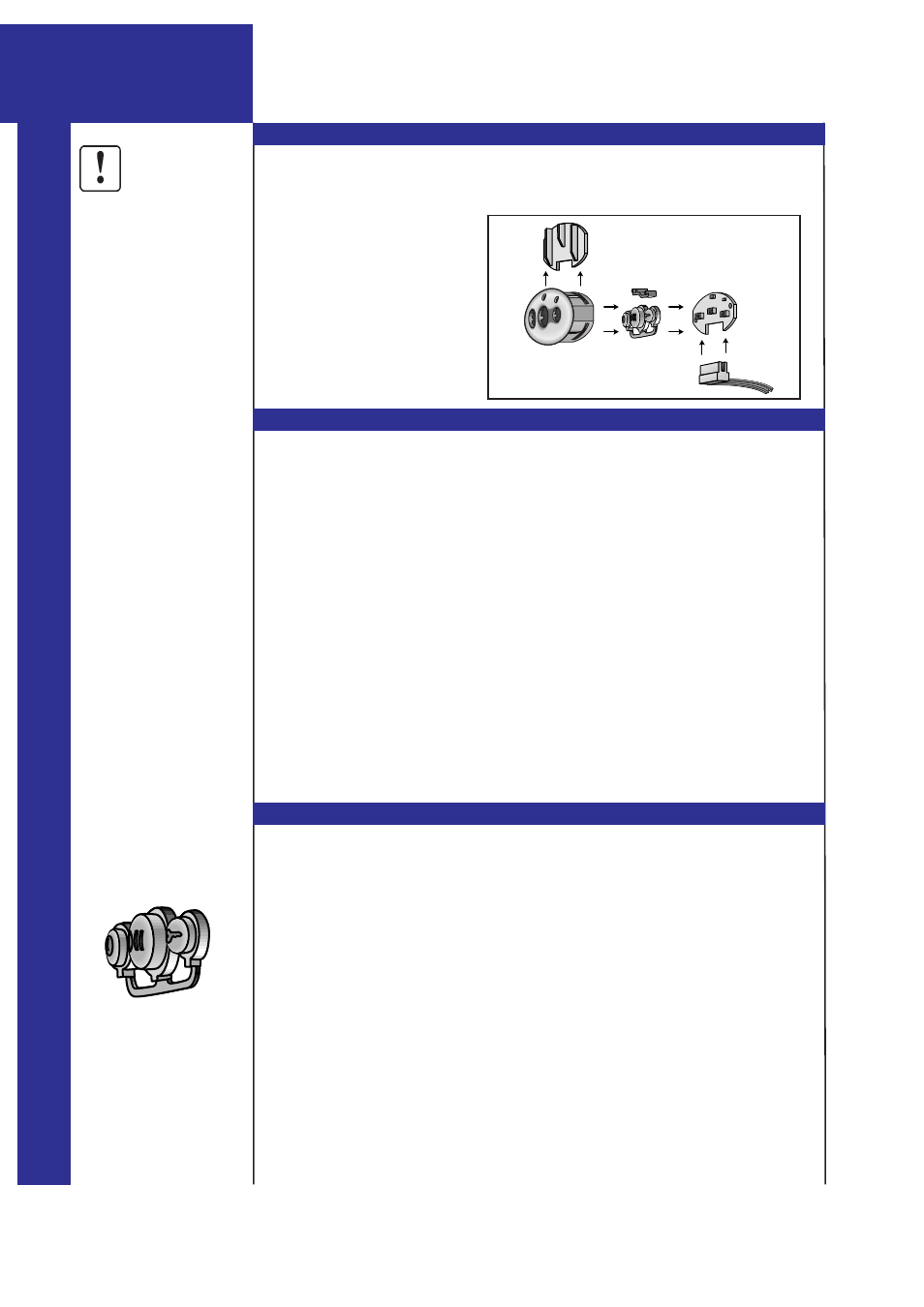
STEP 5.2 DISASSEMBLING THE INTEGRATED BADGE ASSEMBLY
There are several different colored Integrated badges to choose from. They
include black, chrome, satin & brass. Two color options are provided with
your machine, other options are available from your local Dealer.
There are five parts to the
Integrated Badge Assembly.
They are as follows:
1.
Integrated Badge
2.
Button Badge
3.
Light Pipe
4.
Electronics Board
5.
Badge Cover
6.
Wires
5.2.1
Remove Badge Cover from the Integrated Badge.
At the back of the Integrated Badge, slide the Badge Cover away from the wire terminals.
5.2.2
Remove Electronics Board.
Gently hold the wires to remove the Electronics Board. Care should be taken not to
handle the front or back of the Electronics Board or touch inside the wire terminals.
5.2.3
Remove the Light Pipe.
Gently tap the Integrated Badge upside down on a hard surface until the Light Pipe comes
away or insert a pen or pencil into the front side of the Integrated Badge to either one of
the two small holes.
5.2.4
Once you have removed the Electronics Board, Badge Cover and Light Pipe, you can
assemble the electronics board into a badge of another color.
STEP 5.3 ASSEMBLING THE INTEGRATED BADGE
5.3.1
Insert the Button Badge into the back of the Integrated Badge. Do not break any of the
buttons away from the Connection Runner.
5.3.2
Insert the Light Pipe into the Integrated Badge.
Insert the Light Pipe with the circular ends into the small holes.
5.3.3
Insert the Electronics Board with care, behind the Button Badge.
When installing the Electronics Board, handle only the wires and do not touch the face or
back of the Electronics Board or inside the wire terminals.
5.3.4
Slide the Badge Cover into the slot on top of the Integrated Badge.
I
N
T
E
G
R
A
T
E
D
P
R
O
D
U
C
T
O
N
L
Y
Connection Runner
á
Button Badge
1.
2.
3.
4.
5.
6.
Page DS_15
To avoid electric shocks
and damage to electronic
components, the
integrated badge should
be disconnected from the
DishDrawer when
changing the badge
enclosure.
IMPORTANT