L. install horizontal termination cap – Heat & Glo Fireplace SLR (COSMO) User Manual
Page 42
Heat & Glo • SLR • 2143-900 Rev. B • 7/08
42
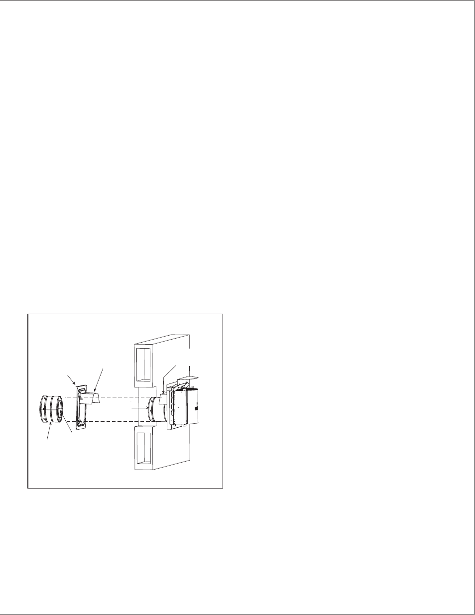
Figure 10.22 Venting through the wall
Note: When using termination caps with factory-supplied heat
shield attached, no additional wall shield fi restop is required on
the exterior side of a combustible wall.
L. Install Horizontal Termination Cap
WARNING! Risk of Fire! The telescoping fl ue section
of the termination cap MUST be used when connecting
vent.
• 1-1/2 (38 MM) MINIMUM OVERLAP OF FLUE TELE-
SCOPING SECTION IS REQUIRED.
FAILURE TO MAINTAIN OVERLAP MAY CAUSE OVER-
HEATING AND FIRE.
• Vent termination must not be recessed in the wall. Siding
may be brought to the edge of the cap base.
• Flash and seal as appropriate for siding material at
outside edges of cap.
• When installing a horizontal termination cap, follow
the cap location guidelines as prescribed by current
ANSI Z223.1 and CAN/CGA-B149 installation codes
and refer to Section 6 of this manual.
CAUTION! Risk of Burns! Local codes may require in-
stallation of a cap shield to prevent anything or anyone
from touching the hot cap.
NOTICE: For certain exposures which require superior
resistance to wind-driven rain penetration, a fl ashing kit and
HRC caps are available. When penetrating a brick wall, a
brick extension kit is available for framing the brick.
INTERIOR
HEAT SHIELD OR
EXTENDED
HEAT SHIELD
WALL SHIELD
FIRESTOP
HEAT SHIELD
1-1/2 IN. (38 MM) MIN.
OVERLAP
SHEATHING
SLIP SECTION
CAN BE EXTENDED
INNER VENT
OUTER VENT
EXTERIOR