HP Reliable Transaction Router User Manual
Page 20
RTR Terminology
Figure 1–4 Facility Symbol
VM-0822A-AI
A facility name is mapped to specific physical nodes and their
roles using the CREATE FACILITY command.
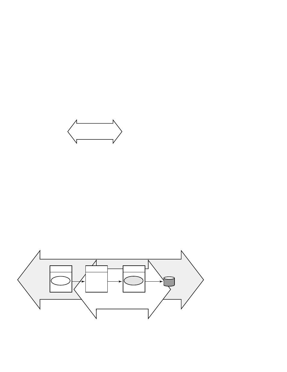
Figure 1–5 shows the logical relationship between client
application, server application, frontends (FEs), routers (TRs),
and backends (BEs) in the RTR environment at a specific
location. The database is represented by the cylinder. Two
facilities are shown (indicated by the large double-headed
arrows), the User Accounts Facility and the General Ledger
Facility. The User Accounts Facility uses three nodes, FE, TR,
and BE, while the General Ledger Facility uses only two, TR and
BE in the configuration shown. Its FEs are on nodes not shown
in the figure, at another location.
Figure 1–5 Components in the RTR Environment
FE
TR
BE
User Accounts Facility
Server
application
General Ledger Facility
VM-0823A-AI
Client
application
1–8 Introduction
- NRM42 (61 pages)
- ProLiant ML370 (49 pages)
- ProLiant ML370 (50 pages)
- ProLiant ML110 G5 (32 pages)
- PC Comm Station Pro 304251-008 (North America) (5 pages)
- 100B-TX (32 pages)
- 3C905B-TX (110 pages)
- EK-STWCT-UG. E01 (45 pages)
- 3800ux (13 pages)
- 5991-6764 (8 pages)
- LTO 4 FC (46 pages)
- StorageWorks Network Attached Storage X3000 (16 pages)
- Ultrium Drive (30 pages)
- ProLiant DL360 (49 pages)
- CD Leycom CFL-512 (5 pages)
- RDX160 (12 pages)
- 345524-B21 (54 pages)
- DT-20 (20 pages)
- SureStore 7115w (136 pages)
- HD1600 (2 pages)
- ProLiant DL160 (38 pages)
- Vectra XW (16 pages)
- D2D4004i (20 pages)
- F1588A (4 pages)
- 94500 (1 page)
- Computer Parts (21 pages)
- MSA50 (8 pages)
- 7750 (32 pages)
- Media Gateways G350 (76 pages)
- P400 Serial (9 pages)
- MSL4048 (4 pages)
- 3C590-TPO (40 pages)
- mv2040 (2 pages)
- AHA-8940 (82 pages)
- ProLiant DL385 (174 pages)
- ProLiant DL385 (47 pages)
- 5300A (19 pages)
- AMD Geode E2047551001R (111 pages)
- 1100d (102 pages)
- xp1024 (2 pages)
- 180 Degree Turn (24 pages)
- procurve J8165A (32 pages)
- 04H8095 (28 pages)
- 744 (154 pages)