be quiet! Dark Base 900 Full-Tower Case (Silver) User Manual
Page 9
8
9
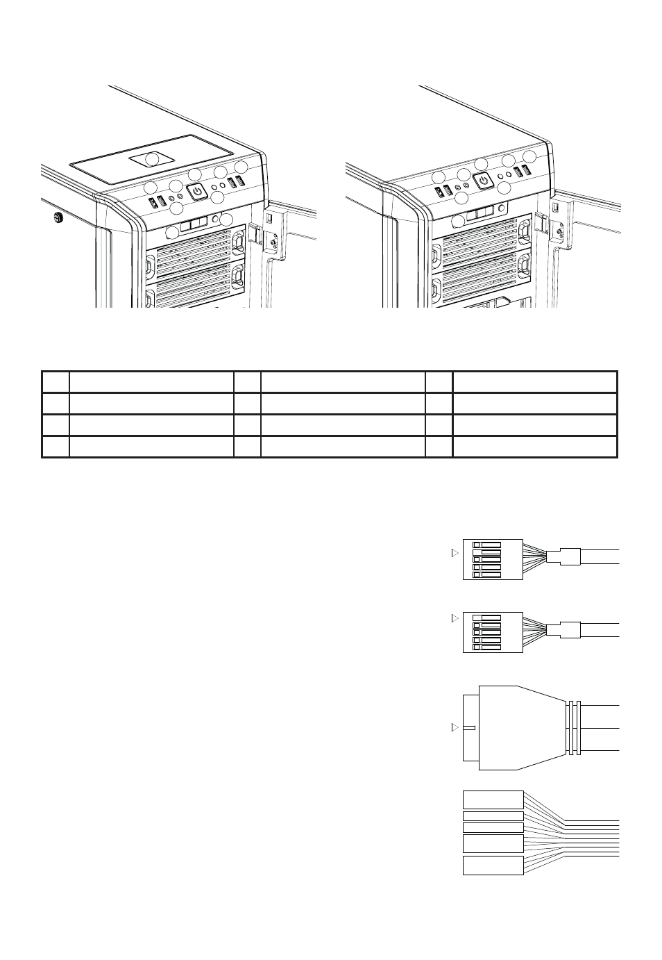
4.1 FRONT I/O AND MEDIA PORTS
A
USB 3.0
E
USB 2.0
I
LED Switch (Pro only)
B
Headphone
F
Microphone
J
QI Charger (Pro only)
C
Power Button / Power LED
G
Reset
D
HDD LED
H
Fan Speed Controller Switch
4.2 I/O PORTS
The function panel has several wire connections that need to be installed.
HD audio (headphone jack/microphone jack)
Find the “Front panel audio headers/pin connectors” on the
motherboard. Plug in the wires according to the motherboard
manual.
USB 2.0
Find the “USB 2.0 Headers/pin connectors” on the motherboard.
Plug in the wires according to the motherboard manual.
USB 3.0
Find the “USB 3.0 Headers/pin connectors” on the motherboard.
Plug in the wires according to the motherboard manual.
Power switch, Power LED, HDD LED, Reset switch
These wires plug into the motherboard where all the front panel
switch/pin connectors functions are located. The motherboard
manual will have a description of where to plug these in, usually
their location is labeled in the motherboard manual.
A
B
C
J
D
E
F
H
G
I
A
B
C
E
G
F
H
D
DARK BASE PRO 900
DARK BASE 900
HD AUDIO
USB
KEY
KEY
KEY
POWER SW
POWERLED +
H.D.D LED
RESET SW
POWERLED -