3 specifications, Table 1-1. specifications, 4 tma vxi27 interconnections – KEPCO TMA VXI-27 User Manual
Page 11: Specifications -2, Tma vxi-27 interconnections -2
1-2
TMA VXI-27 101602
1.3
SPECIFICATIONS (SEE TABLE 1-1)
1.4
TMA VXI-27 INTERCONNECTIONS
A shielded two (2) wire twisted-pair cable equipped with a 9 pin D-type, male, plug-in connector
(supplied) is used to connect the TMA VXI-27 with the power modules. Input power and input/
output signals are provided through the VXI backplane (see Figure 1-2).
An opto-isolated, active high or non-isolated, active low, emergency shutdown input is provided
on the 15 pin D-type female connector located on the front pane (see PAR. 3.1.2.1)l. On the
same connector 2 additional lines provide a normally open contact indicating the proper func-
tioning of the internal microsystem (Discrete Fault line). If either a serious malfunction or a cata-
strophic error occurs, the contacts will close (see PAR. 3.1.2.2)
In configurations where power modules are daisy chained on the IEEE 1118 control bus (see
Figure 1-2), the last power module control bus outlet (in the daisy chain) must be terminated
with the IEEE Control Bus Terminator supplied with the controller to reduce spurious noise and
provide proper impedance matching. The terminator supplied is a 9-pin, D-type connector; for
Kepco MAT Power Supplies with a round 5 pin connector use the 5 pin terminator listed in Table
1-2.
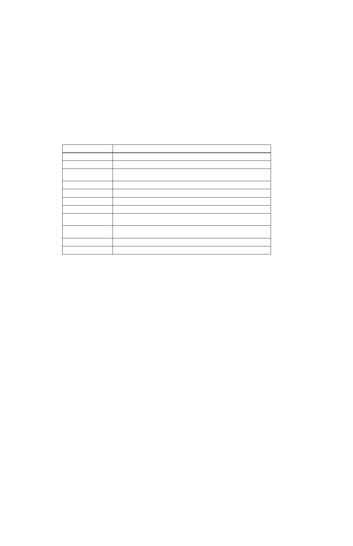
TABLE 1-1. SPECIFICATIONS
SPECIFICATION
DESCRIPTION
Device Type
Message-based
Device Substates
Initialize, Configure, Normal Operation
Applicable
VXI Commands
See Table 3-2.
Addresses
Static, configurable between 1 and 254 using DIP switch (see PAR. 2.2.1).
Manufacturer ID
380410, (0EDCH), read from register 0
Address Space
A16, normal handshake only
Programmable Interrupt
Generates Request True or Request False events
Interrupt Priority
Software assigned (via Slot 0 Controller) from 0 to 7;
0 = no interrupt (default),1 = highest priority, 7 = lowest priority
Capabilities
Message-based Device with Word Serial Capabilities; VXIbus Instrument Protocol;
I4 Class VXI Instrument
Input Power Requirement
Approximately 2A from +5V backplane of VXI.
Physical Dimensions
See Outline Drawing, Figure 1-3.
FIGURE 1-1.