S5500-28f-ei – H3C Technologies H3C S5500 Series Switches User Manual
Page 14
6
(3) Grounding screw
(4) Interface card slot 1 (MOD1)
(5) Interface card slot 2 (MOD2)
NOTE:
The S5500-52C-EI is shipped with the two expansion interface card slots covered by filler panels. You can
select one or two interface cards for your switch as needed. For the interface cards available for the
S5500-EI Switch Series, see "
." For how to install an interface card, see "
."
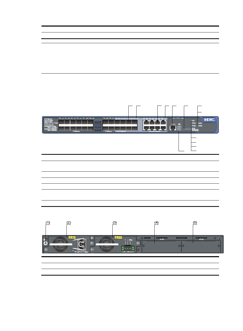
S5500-28F-EI
Figure 6 Front panel of the S5500-28F-EI switch
(1) SFP port
(2) SFP port status LED
(3) 10/100/1000 Base-T auto-sensing Ethernet
port
(4) 10/100/1000 Base-T auto-sensing Ethernet port
status LED
(5) Console port
(6) Port status LED mode switching button
(7) Interface card 1 status LED (MOD1)
(8) Interface card 2 status LED (MOD2)
(9) System status LED (SYS)
(10) Hot swappable power module 1 status LED (PWR1)
(11) Hot swappable power module 2 status LED
(PWR2)
(12) Port mode LED (Mode)
(13) Seven-segment LED
Figure 7 Rear panel of the S5500-28F-EI switch
(1) Grounding screw
(2) Hot swappable power module 1 (a PSR150-A)
(3) Hot swappable power module 2 (a PSR150-D)
(4) Interface card slot 1 (MOD1)
(5) Interface card slot 2 (MOD2)
(2)
(4)
(5)
(6)
(8)
(9)
(10)
(11)
(12)
(13)
(7)
(1)
(3)