ATL Telecom AM2048 User Manual
Page 9
ATL TELECOM USER GUIDE
AM2048A
15
This chapter describes the basic steps that are required to set up a system using the DSL
Modem.
It is recommended that a pair of units is set up back-to-back and working correctly in the
desired operational mode before deployment.
4.1
CONNECTION OF PROTECTIVE EARTH
If it is required to connect the G.703 port to a circuit that is defined as TNV, then a protective
earth must be connected to the earth bond stud on the rear panel. See the Safety Statements
at the front of this User Guide.
If the unit is power fed then a functional earth must be connected to the earth bond stud on
the rear panel to provide a discharge path to ground for ESD protection. See the ESD warning
at the front of this User Guide.
4.2
WARNING - DC POWERING DIRECT FROM EXCHANGE BATTERY
If the installation requires that the –48V is referenced to earth (as opposed to using a floating
DC input) please ensure that the AM2048 is the special DC powered option.
Please refer to the order codes in Appendix B.
4.3
POWER ON SEQUENCE
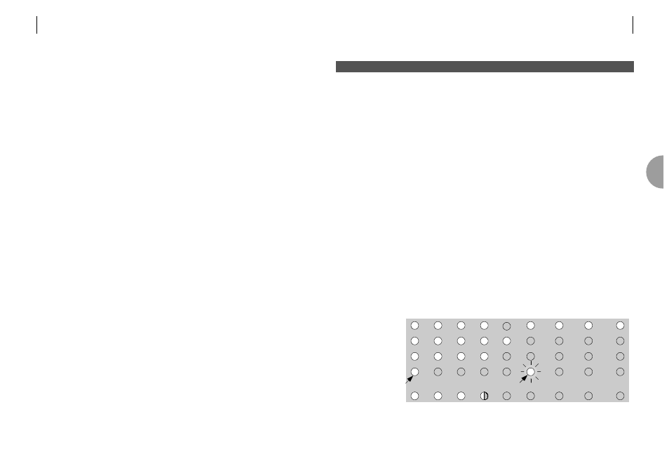
With no DTE or line connected to the AM2048 on power up, the LED colour test sequence is
displayed (RED - GREEN - AMBER) followed by the self test indication as follows:
Prior to the sequence starting, a random pattern may appear momentarily.
User
Master
Test
Local
Loop
Loop
Back
Rem
Loop
RED
GREEN
AMBER
SELF TEST
INITIALISED
Green
Flashing red
Status
Line 1
Line 2
4
I N S T A L L A T I O N
4
14
ATL TELECOM USER GUIDE
AM2048A
On the rear panel there are the following connectors:
Power input (depending on the model)
85 - 250 Volt mains socket
IEC 320
–48V DC supply inlet socket
3-pin mini-fit
Line interface
8-way RJ45 (Copper)
Data Ports (depending on module fitted)
G.703 120 ohm
8-way RJ45
G.703 75 ohm
BNC
X.21
15 way D-type female
V35
34 way MRAC female
10BaseT/100BaseT
8-way RJ45
USB
USB type B (Slave)
The data interface connector type will be from one of the four user-specified interfaces
available. They are detailed in section 7.5. The plastic housing contains the main PCB.
The plastic case has an internal metallised layer for EMC screening purposes.
Also included is a 1.5m mains lead fitted with a country variant mains plug (mains models
only) and a 3 metre screened, stranded, Category 5 line cord terminated in 8-way RJ45 plugs
at both ends.
A VT100 Management connection cable is also available.
The overall dimensions of the unit are 274mm(L) x 251mm(W) x 55mm(H).