ATL Telecom AM2048 User Manual
Page 21
ATL TELECOM USER GUIDE
AM2048A
39
7.5.2
X.21
ITU Recommendation V.11 refers to ISO 4903 for the connector pin-out.
The clock rate is set up using the “Configuration > User Port” Menu.
Select the required value of N for Nx64K circuits.
DTE – DCE mode, and X-B mode are selected using the hardware links on the X.21 interface
module.
Circuit
G
T
R
C
I
S
B
X
Pins
A B
8
2 9
4 11
3 10
5 12
6 13
7 14
7 14
Interchange Circuit Name
Signal ground or Common Return
Transmit
Receive
Control
Indication
Signal Element Timing
Byte Timing
DTE Signal Element Timing
Definition
From DTE to DCE
From DCE to DTE
From DTE to DCE
ON during Data
OFF during Control
From DCE to DTE
ON during Data
OFF during Control
From DCE to DTE
T and R change at
OFF to ON of S
From DCE to DTE
OFF for the ON period of S
During the last bit of the octet
MK I, not used
MK II, From DTE to DCE
7
38
ATL TELECOM USER GUIDE
AM2048A
7.5
INTERFACE MODULES
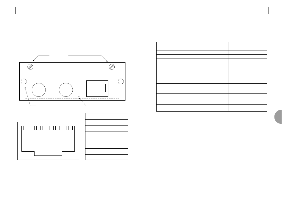
7.5.1
G.703
The 75 ohm interface connectors are BNC.
The 120 ohm interface connector is RJ45.
Selection of the interface is carried out in the “Configuration > User Port” menu.
1
3
2
4
6
5
RJ45
1
2
4
5
6
TxA
TxB
RxA
RxB
n.c.
n.c.
7
8
3
7
8
screen
screen
120 ohm
75 ohm IN
75 ohm OUT
G703 75/120 PIM
Fixing Screws
Card Extractor Grip
PCB Position