ATL Telecom AM2048 User Manual
Page 22
ATL TELECOM USER GUIDE
AM2048A
41
7.5.4
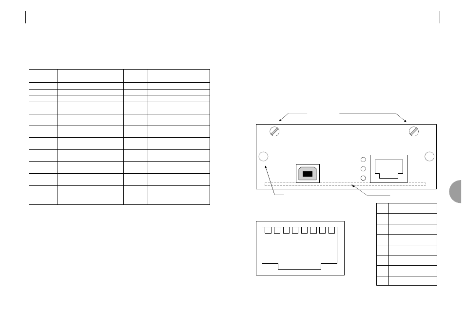
e-PIM
The Ethernet port is 10BaseT/100BaseT and the connector is RJ45, the pin-out is shown below.
When connecting the Ethernet port directly to a PC, a crossover cable is required.
Ethernet Indicator LEDS
Rx
Packet Received
Tx
Packet transmitted
LINK
Link Active
The USB port is a slave and can be connected to a PC using a standard USB Peripheral
Cable A - B.
Please refer to the e-PIM User Guide for further information.
1
3
2
4
6
5
PANEL VIEW
1
2
3
4
5
6
TX+
TX-
Rx+
n.c.
n.c.
Rx-
8
7
7
8
n.c.
n.c.
10BaseT
Rx
USB
e-PIM
Fixing Screws
Card Extractor Grip
PCB Position
Tx
LINK
7
40
ATL TELECOM USER GUIDE
AM2048A
7.5.3
V.35
ITU Recommendation V.35 refers to ISO 2593 for the connector pin out.
Circuits marked
φ
are balanced V.35, unmarked circuits are to V.28.
Circuit marked
∆
is only implemented in DTE mode.
The clock rate is set up using the “Configuration > User Port” Menu.
Select the required value of N for Nx64K circuits.
DTE – DCE mode may be selected using Links 1 and 2.
Circuit
102
103
φ
104
φ
105
106
107
109
113
φ∆
114
φ
115
φ
140
141
142
Pins
A B
B
P S
R T
C
D
E
F
U W
Y AA
V
X
N
L
NN
Interchange Circuit Name
Signal ground or Common Return
Transmitted Data
Received Data
Request To Send (RTS)
Ready For Sending (RFS)
Data Set Ready (DSR)
Received Signal Detector
Terminal Signal Element Timing
Transmitter Signal Element Timing
Receiver Signal Element Timing
Remote Loop-back
Local Loop-back
Test Indicator
Definition
From DTE to DCE
From DCE to DTE
ON transmit Data
OFF transmit binary 1
ON DCE ready to accept data
OFF DCE not ready
ON DCE ready to operate
OFF DCE not ready to operate
ON line signal is good
OFF line signal out of limits
103 changes at
OFF to ON of 113
103 changes at
OFF to ON of 114
Centre of bit on 104
ON to OFF on 115